
Plasma waste gas treatment device

A waste gas treatment device and plasma technology, which are applied in gas treatment, separation method, dispersed particle separation and other directions, can solve the problems of difficult to apply coating equipment waste gas treatment, complex plasma technology structure and poor waste gas treatment effect, etc. Satisfy the effect of exhaust gas treatment, ensure long-term normal treatment requirements, and simple structure

Inactive Publication Date: 2017-04-26
DEQING HUAMENG WOODWORK
View PDF9 Cites 1 Cited by
  • Summary
  • Abstract
  • Description
  • Claims
  • Application Information

AI Technical Summary

Problems solved by technology

[0004] At present, the technology of using plasma for waste gas treatment is a mature technology. There are many kinds of plasma waste gas technologies disclosed in the Chinese patent bulletin. For example, the patent application number is: 200980135309.9 discloses a "plasma treatment method and equipment" , the structure of the plasma technology disclosed in this patent application is quite complicated, so it is difficult to apply to the exhaust gas treatment in the existing coating equipment; and the exhaust gas treatment equipment with simple structure has poor exhaust gas treatment effect, etc. Problems, especially for small-scale waste gas treatment of some small-scale coating equipment, there is currently no plasma waste gas treatment equipment that meets the requirements of waste gas treatment, has a simple structure, is easy to install and maintain, and can ensure the normal treatment of waste gas for a long time

Method used


Image

  • Plasma waste gas treatment device
  • Plasma waste gas treatment device

Examples


Embodiment Construction

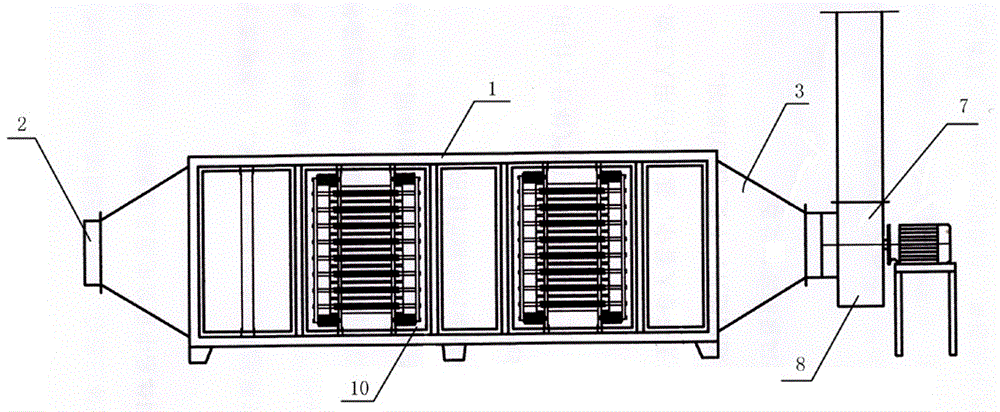
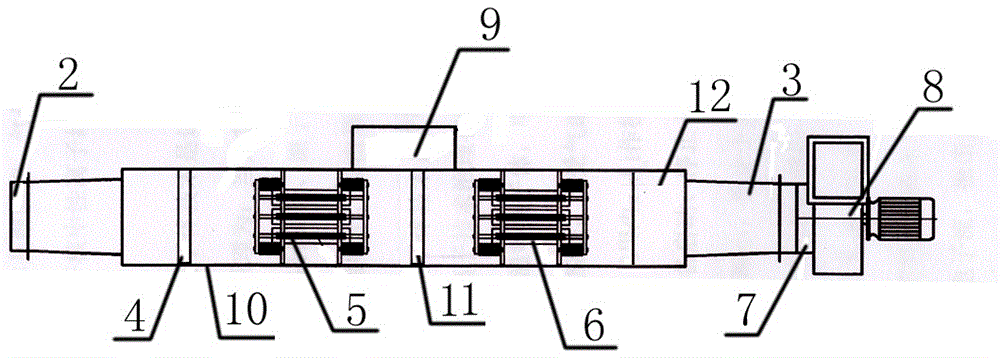
[0012] The present invention will be described in detail below in conjunction with accompanying drawing: figure 1 , 2 As shown, the plasma exhaust gas treatment device according to the present invention includes a rectangular parallelepiped horizontal casing 1, and the two ends of the casing 1 are respectively provided with an exhaust gas inlet 2 and an exhaust gas treatment outlet 3. Starting from the waste gas inlet, a first wire mesh filter 4, a primary plasma treatment core 5, a second wire mesh filter 11 and a secondary plasma treatment core 6 are arranged in sequence; at the waste gas treatment outlet 3 An exhaust gas treatment induction pipe 7 is connected, and an exhaust fan 8 is arranged on the exhaust gas treatment induction pipe 7 .

[0013] As shown in the figure, an electric control cabinet 9 is installed on one side of the housing 1, and an inspection port 10 is provided on the other side at least corresponding to the plasma processing core installed, and the in...


PUM


Abstract

The invention relates to a plasma waste gas treatment device which comprises a cuboid horizontal type shell. A water gas inlet and a waste gas treatment outlet are formed in the two ends of the horizontal type shell. The plasma waste gas treatment device is characterized in that a first metal wire gauze strainer, a first-stage plasma treatment core, a second metal wire gauze strainer and a second-stage plasma treatment core are sequentially arranged in the shell from the waste gas inlet; a waste gas treatment air inducing pipe is connected to the waste gas treatment outlet, and an air draft fan is arranged on the waste gas treatment air inducing pipe; and an electronic control cabinet is installed on one side of the shell, overhauling openings are formed at least in the positions, corresponding to the plasma treatment cores, of the other side of the shell, and opened doors or movable doors are arranged on the overhauling openings. The plasma waste gas treatment device has the beneficial effects of being simple in structure, safe, reliable, easy to operate, convenient to install and maintain, low in running cost, high in treatment efficiency, capable of guaranteeing that waste gas is normally treated for a long time, capable of meeting the requirement for the waste gas treatment effect of coating equipment and the like.

Description

technical field [0001] The invention relates to a plasma exhaust gas treatment device, which is mainly used for exhaust gas treatment of coating equipment and belongs to the technical field of exhaust gas treatment. Background technique [0002] Plasma is the fourth state of matter after the three states of solid, gas, and liquid. It is composed of positive ions, negative ions, electrons and neutral ions. Because the total number of positive and negative charges in the system is equal, it is called "plasma". . [0003] Low-temperature plasma technology is a new technology for waste gas treatment developed in recent years. The principle of low-temperature plasma treatment of waste gas is: when the applied voltage reaches the gas discharge voltage, the gas is broken down to produce electrons, various ions, atoms and free A mixture of radicals; the degradation of pollutants by low-temperature plasma is to use the action of these high-energy electrons, free radicals and other a...

Claims


Application Information

Patent Timeline
IPC IPC(8): B01D53/32
CPCB01D53/32B01D2258/0258
Inventor 涂兴家
Owner DEQING HUAMENG WOODWORK
Learn More