
Center hole perforating equipment used for gear production

A technology of punching equipment and center hole, which is used in drilling/drilling equipment, boring/drilling, metal processing equipment, etc., can solve problems such as low production efficiency, affecting punching work, and limiting the scope of staff activities. , to improve work efficiency and ensure the effect of cleaning

Inactive Publication Date: 2017-04-26
泸州开士乐工程技术有限责任公司
View PDF0 Cites 0 Cited by
  • Summary
  • Abstract
  • Description
  • Claims
  • Application Information

AI Technical Summary

Problems solved by technology

[0003] Punching the center hole of the gear blank is an indispensable and important link in gear processing, but the existing gear center hole punching equipment still has some deficiencies in use. First, the feeding method is mostly manual loading. , the production efficiency is low during processing and production, and it is not suitable for mass production; secondly, a large amount of debris will be generated during the drilling process, and these debris will affect the normal drilling work if they are not processed and accumulated. At present, most of the cleaning methods are manual. cleaning, thus severely restricting the scope of movement of the staff

Method used


Image

  • Center hole perforating equipment used for gear production
  • Center hole perforating equipment used for gear production

Examples


Embodiment Construction

[0019] The following will clearly and completely describe the technical solutions in the embodiments of the present invention with reference to the accompanying drawings in the embodiments of the present invention. Obviously, the described embodiments are only some, not all, embodiments of the present invention.

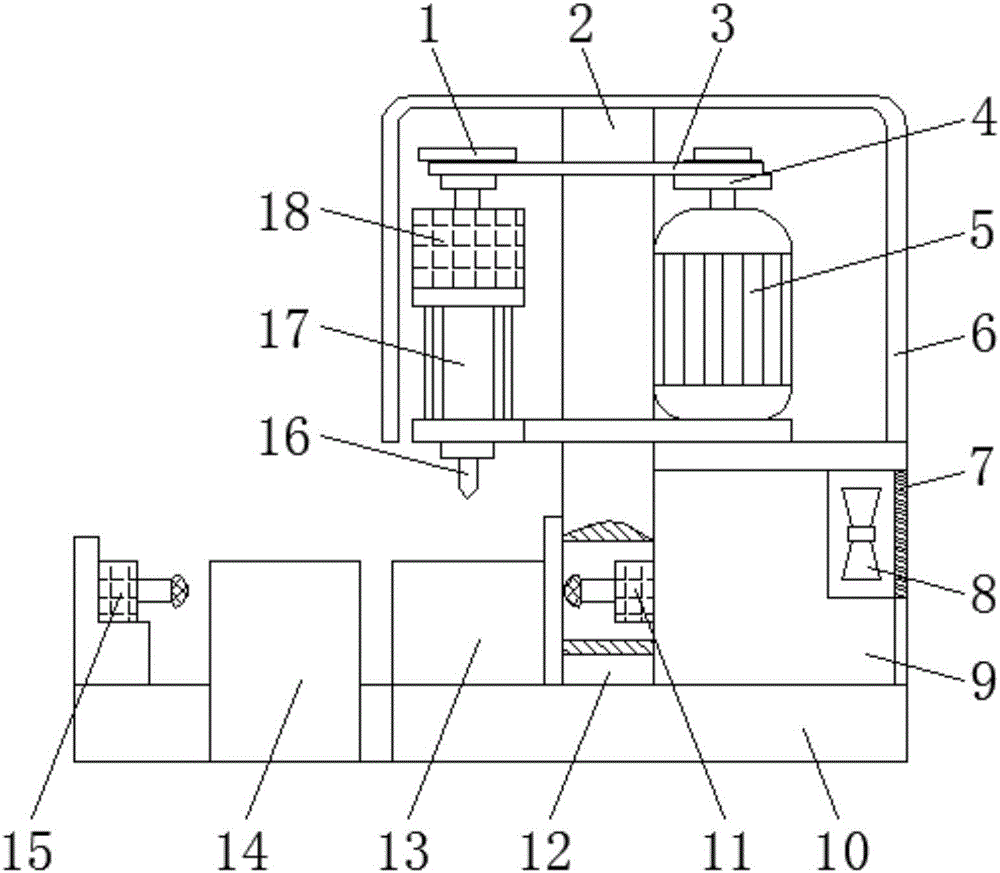
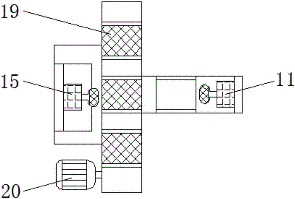
[0020] refer to Figure 1-2 , a center hole punching device for gear production, comprising a punching device body 2 and a conveyor belt 14, a first drive motor 5 is installed on one side of the punching device body 2, and a first drive motor 5 is installed on the other side of the punching device body 2 Speed ​​reducer 18, first multi-stage gear 1 is installed on the top of speed reducer 18, second multi-stage gear 4 is installed on the top of first drive motor 5, and second multi-stage gear 4 is connected with first multi-stage gear by transmission belt 3 1 transmission connection, a telescopic cylinder 17 is installed under the reducer 18, and a drill bit 16 is in...


PUM


Abstract

The invention discloses center hole perforating equipment used for gear production. The center hole perforating equipment comprises a perforating equipment body and a conveying belt. A first drive motor is installed on one side of the perforating equipment body, and a reducer is installed on the other side of the perforating equipment body. A first multistage gear is installed on the reducer. A second multistage gear is installed on the first drive motor. The conveying belt is installed on one side of the perforating equipment, a push rod is arranged at one side of the conveying belt, materials in material grooves in the conveying belt are pushed under a perforating workbench through the push rod and then perforated, and finished products are pushed back into the material grooves through a push rod at the perforating equipment side after perforating is completed; and a dust collecting bin is arranged at one side of the perforating workbench, a fan is installed in the dust collecting bin, and a ventilating hole in one side of the dust collecting bin has high suction force, so that chippings generated during perforating on the workbench are sucked into the dust collecting bin.

Description

technical field [0001] The invention relates to the technical field of gear processing equipment, in particular to a center hole punching equipment for gear production. Background technique [0002] The application of gears in transmission has appeared very early. At the end of the 19th century, the principle of generative gear cutting method and special machine tools and cutting tools using this principle appeared one after another. With the development of production, the stability of gear operation was paid more attention. [0003] Drilling the center hole of the gear blank is an indispensable and important link in gear processing, but the existing equipment for drilling the center hole of the gear still has some deficiencies in use. First, the feeding method is mostly manual feeding. , the production efficiency is low during processing and production, and it is not suitable for mass production; secondly, a large amount of debris will be generated during the drilling proc...

Claims


Application Information

Patent Timeline
Patent Type & Authority Applications(China)
IPC IPC(8): B23B41/00B23Q7/00B23Q11/00
CPCB23B41/00B23Q7/00B23Q11/0046
Inventor 经廷辉
Owner 泸州开士乐工程技术有限责任公司
Learn More