A durable cutting machine

A durable, bar-breaking machine technology, used in ceramic molding machines, manufacturing tools, etc., can solve the problems of wire breakage, frequent replacement or maintenance of steel wires, etc., to achieve a flat section, increase normal working time, increase The effect of stability

Inactive Publication Date: 2018-10-09
四川联腾电子科技有限公司
View PDF9 Cites 0 Cited by
  • Summary
  • Abstract
  • Description
  • Claims
  • Application Information

AI Technical Summary

Problems solved by technology

[0004] Based on the above technical problems, the present invention provides a durable slitting machine, thereby solving the technical problem that the steel wire of the existing slitting machine is easy to break, and the steel wire needs to be replaced or repaired frequently

Method used


Image

  • A durable cutting machine
  • A durable cutting machine
  • A durable cutting machine

Examples


Embodiment 1

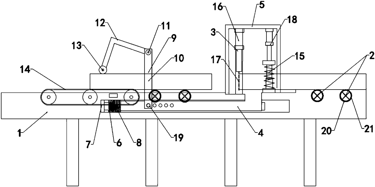
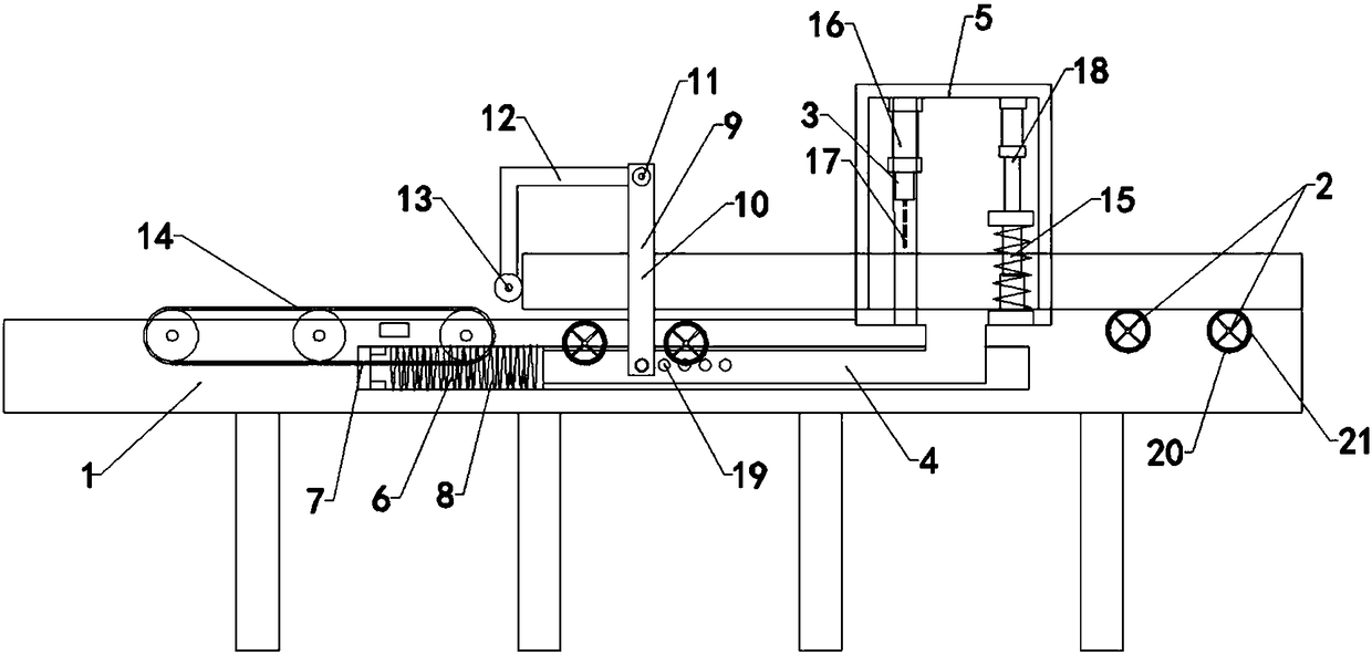
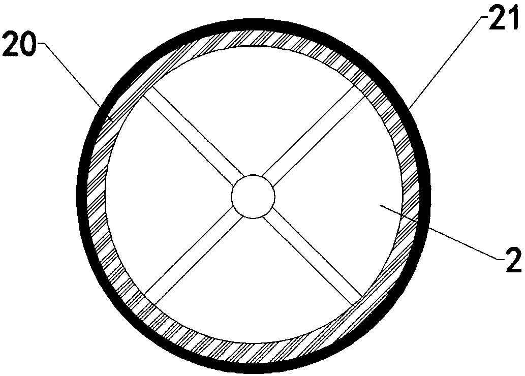
[0034] A durable sliver breaking machine, comprising a main frame 1, a conveying roller 2 arranged at the middle and right end of the main frame 1, a fast belt 14 arranged at the front end of the sliver breaking machine in the output direction, and a sliding belt that can slide along the length direction of the main frame 1. The rod 4 is characterized in that: the middle part of the sliding rod 4 is provided with a drive frame 9; the sliding rod 4 is provided with a reset device 6 at one end of the output direction of the slitting machine, and the other end is provided with a gantry 5; the gantry 5 The inside is respectively provided with a cutting device 3 and a compacting device 15; the cutting device 3 includes a cutting cylinder 16 arranged inside the gantry frame 5 and a sheet cutter 17 connected to the cutting cylinder 16, and the cutting cylinder 16 controls the sheet cutter 17 moves up and down; the compaction device 15 includes a compaction cylinder 18 fixed on the cro...

Embodiment 2

[0036] This embodiment is further improved on the basis of Embodiment 1. The drive frame 9 includes a support rod 10 fixedly connected to the sliding rods 4 on both sides, a rotating shaft 11 arranged between the two supporting rods 10, and a movable shaft that can rotate along the rotating shaft 11. Door 12; the movable door 12 is made up of a right-angle steel plate and a roller 13 arranged on the top of the right-angle steel plate. Since the driving frame 9 and the gantry frame 5 are respectively fixed on the sliding rod 4, the sliding rod 4 can move along the length of the main frame 1. direction sliding, so when the mud rod passes through the gantry 5 and travels to the position of the driving frame 9, the mud rod is in contact with the drum 13, thereby driving the driving frame 9, the sliding rod 4 and the gantry 5 to move forward together, when the mud rod and the gantry When the frame 5 speeds are consistent, the cutting device 3 on the portal frame 5 cuts off the mud r...

Embodiment 3

[0038] This embodiment is further improved based on Embodiment 2. The sliding rod 4 is horizontally provided with a plurality of limiting holes 19; . Since the horizontal distance between the cylinder 13 provided at the top of the driving frame 9 and the sheet cutter 17 is equal to the length of the mud bar that needs to be cut, so the position of the driving frame 9 can be adjusted by the limit hole 19 to obtain the required mud bar length.


PUM


Abstract

The invention belongs to the technical field of brick-making machinery and equipment, and provides a durable strip breaking machine, which includes a main frame, a conveying roller, and a sliding rod. A driving frame is arranged in the middle of the sliding rod; One end is provided with a reset device, and the other end is provided with a gantry frame; the inside of the gantry frame is respectively provided with a cutting device and a compacting device; the cutting device includes a cutting cylinder installed inside the gantry frame and a sheet cutter connected to the cutting cylinder. Knife and cutting cylinder control the sheet cutter to move up and down; the compacting device includes a compacting cylinder fixed on the beam at the top of the gantry frame, the compacting cylinder is connected with a pressing plate, and a compacting spring is arranged between the pressing plate and the gantry frame . This durable sliver cutting machine uses a sheet cutter instead of the traditional steel wire. The strength of the cutter is greater than that of the steel wire, so it is not easy to be damaged, which reduces the manpower and material resources required for replacing the steel wire, and increases the normal working time of the production system.

Description

technical field [0001] The invention belongs to the technical field of brick-making machinery and equipment, in particular to a durable strip breaking machine with reduced maintenance and long service life. Background technique [0002] In the process of making bricks, the brick making machine first extrudes the mud material into continuous mud strips, and then the continuous mud strips are cut into required length strips by the strip breaking machine during the transmission process and sent to the blank cutting machine , Cut into blocks with the same thickness by a cutting machine, and then perform drying, roasting and other processes to form finished products. The existing brick and tile production line has higher and higher requirements for slitting. The traditional slitter cutting machine is outdated, requiring manual slitting. The labor intensity is relatively high, and the efficiency is relatively low. [0003] Patent No. CN201120006843.4 discloses a sliver breaking m...

Claims


Application Information

Patent Timeline
Patent Type & Authority Patents(China)
IPC IPC(8): B28B11/16
CPCB28B11/161B28B11/166
Inventor 谭强
Owner 四川联腾电子科技有限公司
Why Eureka
Try Eureka