Belt conveyor emergency stop operating device

A technology of operating device and belt conveyor, which is applied in the direction of conveyor control device, transportation and packaging, conveyor objects, etc., can solve the problems of transfer machinery damage, potential safety hazards, troublesome cable installation and construction, etc., to improve safety reliability, Avoid mechanical damage and ensure beautiful and smooth effects

Active Publication Date: 2019-08-23
TIDFORE HEAVY IND
View PDF9 Cites 0 Cited by
  • Summary
  • Abstract
  • Description
  • Claims
  • Application Information

AI Technical Summary

Problems solved by technology

[0004] 1. The cable from the cable bridge to the emergency stop operating device needs to pass through the ground of the main channel of the belt corridor. The installation and construction of the cable is troublesome, which affects the beauty and traffic of the main channel;
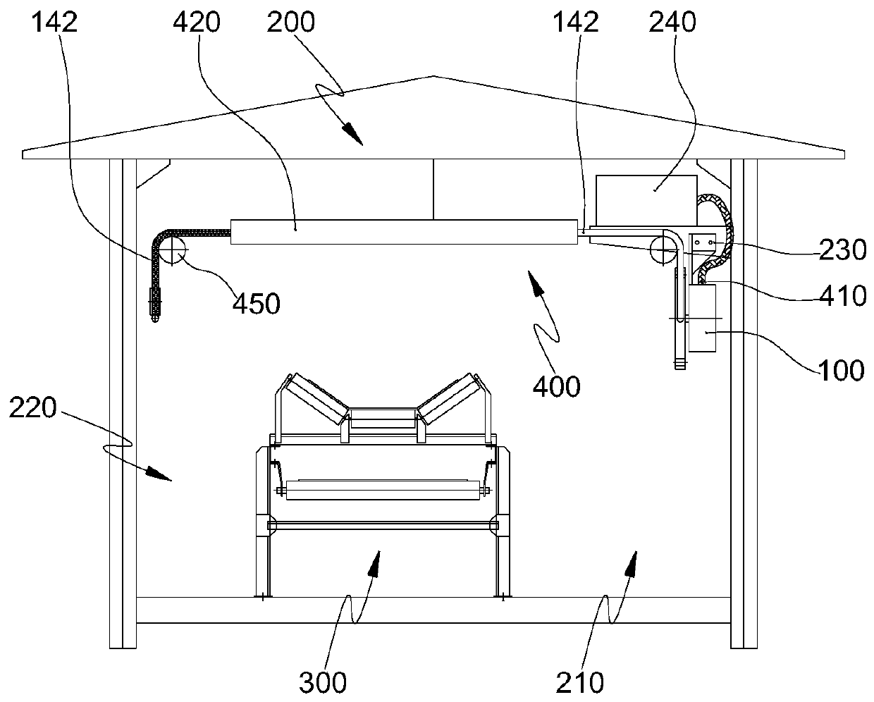
[0005] 2. The pull wire is laid along the belt frame, and the height is lower than the belt surface. When the personnel operate the pull wire, they are easily damaged by the transfer machinery. During the inspection and maintenance of the belt conveyor equipment, it is easy to misuse the pull wire and cause abnormal shutdown. The pull wire is also vulnerable to the pull wire being affected by materials, There are potential safety hazards caused by crushing and erosion caused by flushing water;
[0006] 3. Faults such as belt deviation, tearing, and idler falling off are likely to cause damage to the emergency stop operating device and cable damage. When the belt equipment is washed with water, it is easy to cause water ingress and electrical failure of the emergency stop operating device;
[0007] 4. The pull wire is only installed on one side of the belt rack (the side of the main passage), and the other side (the side of the auxiliary passage) is not installed. Shutdown of the operating device, resulting in a safety accident

Method used


Image

  • Belt conveyor emergency stop operating device
  • Belt conveyor emergency stop operating device
  • Belt conveyor emergency stop operating device

Examples


Embodiment Construction

[0033]Specific embodiments of the present invention will be described in detail below in conjunction with the accompanying drawings. It should be understood that the specific embodiments described here are only used to illustrate and explain the present invention, and are not intended to limit the present invention.

[0034] For the convenience of description, spatially relative terms may be used here, such as "on ...", "over ...", "on the surface of ...", "above", etc., to describe the The spatial positional relationship between one device or feature shown and other devices or features. It will be understood that the spatially relative terms are intended to encompass different orientations of the device in use or operation in addition to the orientation depicted in the figures. For example, if the device in the figures is turned over, devices described as "above" or "above" other devices or configurations would then be oriented "beneath" or "above" the other devices or confi...


PUM


Abstract

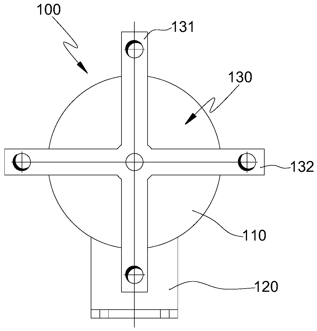
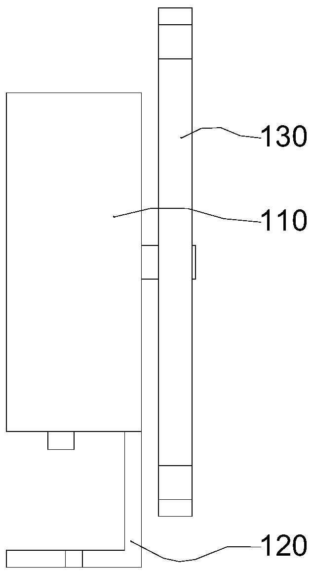
The invention relates to a belt machine emergency stop operation device and belongs to the field of belt conveyors. The belt machine emergency stop operation device comprises an emergency stop switch, a belt passage corridor, a belt machine and a wiring device, wherein the belt machine is arranged in the belt passage corridor and extends along the length direction of the belt passage corridor; the emergency stop switch fixed at the top end of the belt passage corridor comprises a switch body, a pedestal, a pull rod and stay wires; the switch body is a normally open or normally closed contact; the switch body and the stay wires are fixed at the top end of the belt passage corridor through the pedestal; the pull rod is rotatably connected with the switch body and drives the switch body to switch on or off a control loop; the stay wires are arranged on the two sides of the belt machine correspondingly and extend along the length direction of the belt passage corridor; the stay wires which are arranged on the two sides of the belt machine correspondingly and are in driving connection with the pull rod covers channels on the two sides of the belt machine; and when the belt machine encounters failure, an operator can operate the stay wires on any side, so that shutdown of the belt machine is realized timely and quickly and the safe reliability of the belt machine is improved.

Description

technical field [0001] The invention relates to the field of belt conveyors, in particular to an emergency stop operating device, in particular to an emergency stop operating device for a belt conveyor. Background technique [0002] The emergency stop operating device is an essential safety protection device for belt conveyors. It prevents accidents from expanding and causing heavy losses. It has the advantages of convenient installation and reliable switch conversion, and is widely used in on-site production. It is mainly composed of a switch body, a pull rod and a base. The switch body is equipped with a rotating shaft switch, which is provided with a normally open or normally closed contact, which is used to connect or disconnect the control circuit. The pull rod is the operating mechanism of the emergency stop operating device, fixed in the middle On the rotating shaft of the switch body, there are pull wire holes at both ends for connecting the pull wires. The base is ...

Claims


Application Information

Patent Timeline
Patent Type & Authority Patents(China)
IPC IPC(8): B65G43/02
Inventor 胡红才
Owner TIDFORE HEAVY IND
Why Eureka
Try Eureka