
Ditching machine and its control system

A machine and control box technology, applied in the direction of earth mover/shovel, construction, etc., can solve the problems of complex construction conditions, labor-intensive excavation, time-consuming, high cost, saving manpower, avoiding casualties, and small width. Effect

Active Publication Date: 2018-12-07
CHENGWU POWER SUPPLY CO STATE GRID SHANDONG ELECTRIC POWER CO LTD +1
View PDF5 Cites 0 Cited by
  • Summary
  • Abstract
  • Description
  • Claims
  • Application Information

AI Technical Summary

Problems solved by technology

However, in rural or remote areas, the construction conditions are complex, the amount of single project is small, and the cost of using large equipment such as excavators is high; and excavators are large in size and cannot be used in some special geographical environments, for example, in narrow spaces and muddy ground When carrying out cable laying construction under certain conditions, large excavators cannot enter, and manual excavation is labor-intensive and time-consuming

Method used


Image

  • Ditching machine and its control system
  • Ditching machine and its control system
  • Ditching machine and its control system

Examples


Embodiment 1

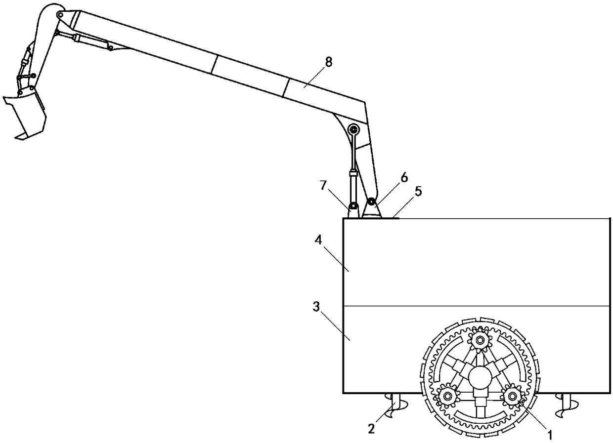
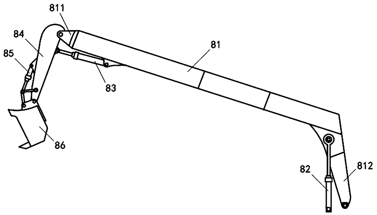
[0055] figure 1 A schematic structural diagram of the ditching machine provided in this embodiment. like figure 1 As shown, the ditching machine of this embodiment includes a control box 3 , an excavating device 8 , a soil loosening device 2 , a traveling device and a soil storage bucket 4 installed above the control box 3 .

[0056] The control box 3 is provided with a control device, a first power device for powering the excavating device 8 and a second power device for powering the traveling device.

[0057] The traveling device is track wheels arranged on both sides of the control box. The track wheel includes a track, a hydraulic support frame for supporting the track, and a first support wheel, a second support wheel, and a third support wheel; internal teeth are formed on the inner side of the track; the first support wheel, the second support wheel, and the third support wheel The wheels are all angle gears, which mesh with the internal teeth on the inner side of th...

Embodiment 2

[0079] This embodiment provides a control system for controlling the operation of the ditching machine, including a remote controller and a control device arranged on the ditching machine; signals are transmitted between the remote controller and the control device through infrared rays or radio waves.

[0080] Wherein, the control device includes a signal receiver, a signal identification unit, a first control signal sending unit and a second control signal sending unit; the signal receiver is used for receiving the remote control signal sent by the remote controller. The signal discrimination unit is used to distinguish the remote control signal as the first remote control signal or the second remote control signal; the first remote control signal is used to control the excavating device to carry out excavation operation; the second remote control signal is used to control the advance and retreat of the traveling device; the first control signal sending unit It is used to sen...


PUM


Abstract

The invention provides a trenching machine and a control system thereof, and belongs to the technical field of ground surface construction engineering. The trenching machine comprises a control box, an excavating device, a travelling device and a soil storage bucket which is mounted above the control box; a control device, a first power device which provides power for the excavating device and a second power device which provides power for the travelling device are arranged in the control box; according to the trenching device and the control system thereof provided by the invention, the travelling device adopts crawler wheels which are arranged on the two sides of the control box; the overall width of the machine is small, and the crawler wheels grip the ground firmly, so that construction can be performed in an area with small space and a muddy ground surface; a soil discharging channel is formed behind an excavating bucket; the soil which is excavated by the excavating bucket can be discharged into the soil storage bucket through the soil discharging channel; redundant garbage cannot be brought to surrounding environment; the machine is controlled to operate by adopting a remote controller, and is not required to be driven by a driver; labour is saved, and the danger of casualties caused by construction in a dangerous environment is also avoided.

Description

technical field [0001] The invention relates to the technical field of ground construction engineering, in particular to a ditching machine and a control system thereof. Background technique [0002] In power planning, in order to avoid potential safety hazards caused by too many overhead cables, when laying cables, transmission lines are often laid underground, which can effectively improve the safety and reliability of the power distribution system. [0003] When laying underground cables, corresponding cable trenches need to be excavated. At present, excavators are often used to complete the excavation of cable trenches. However, in rural or remote areas, the construction conditions are complex, the amount of single project is small, and the cost of using large equipment such as excavators is high; and excavators are large in size and cannot be used in some special geographical environments, for example, in narrow spaces and muddy ground When carrying out cable laying c...

Claims


Application Information

Patent Timeline
Patent Type & Authority Patents(China)
IPC IPC(8): E02F5/02E02F9/20
CPCE02F5/025E02F9/205
Inventor 牛德成惠所信张法忠张振涛王桂莲王瑞兰刘娜贾飞马晨光李丕燕
Owner CHENGWU POWER SUPPLY CO STATE GRID SHANDONG ELECTRIC POWER CO LTD
Learn More