Gas life reverse-circulation negative pressure sand-cleaning method and apparatus

A technology of gas lift reverse circulation and sand cleaning, which is applied in earthwork drilling, wellbore/well components, construction, etc. It can solve the problems of inability to carry out the wellbore, leakage, pressure drop, etc. in the wellbore, and achieve the risk of sand stuck Small size, reduced operating costs, and improved timeliness

Active Publication Date: 2017-04-26
库尔勒施得石油技术服务有限公司
View PDF8 Cites 7 Cited by
  • Summary
  • Abstract
  • Description
  • Claims
  • Application Information

AI Technical Summary

Problems solved by technology

And because the pressure in the wellbore decreases for a long time, the liquid level drop is no longer located at the wellhead, but leaks in the wellbore, and the sand in the wellbore cannot be brought out of the wellbore by normal circulation.

Method used


Image

  • Gas life reverse-circulation negative pressure sand-cleaning method and apparatus
  • Gas life reverse-circulation negative pressure sand-cleaning method and apparatus
  • Gas life reverse-circulation negative pressure sand-cleaning method and apparatus

Examples


Embodiment 1

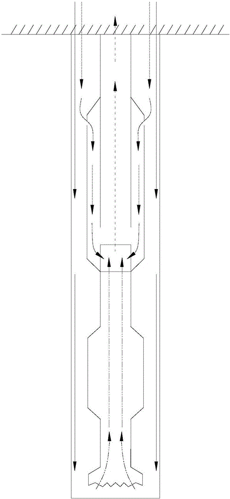
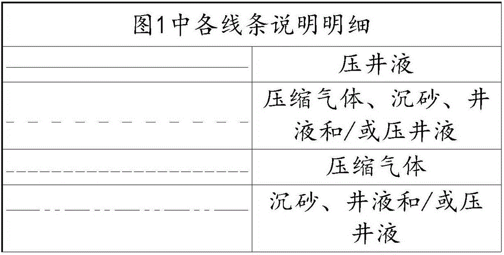
[0028] Such as figure 1 The present invention shown provides a gas lift reverse cycle negative pressure sand cleaning method, which includes the following steps: injecting compressed gas into the sand cleaning device, the compressed gas is expanded in the sand cleaning device, and the inside of the sand cleaning device The pressure in the wellbore forms a negative pressure relative to the pressure in the wellbore. Under the action of the negative pressure, the sand and well fluid in the wellbore enters the sand cleaning device and is discharged by gas lift in the sand cleaning device. Achieve sand removal. By adopting the above technical scheme, the negative pressure is maintained at the bottom of the wellbore during the whole process of sand cleaning, which can effectively prevent sand from sinking into the formation and effectively protect the reservoir; during the sand cleaning process, there is no loss, no pollution to the formation, no need to return to production, and high...

Embodiment 2

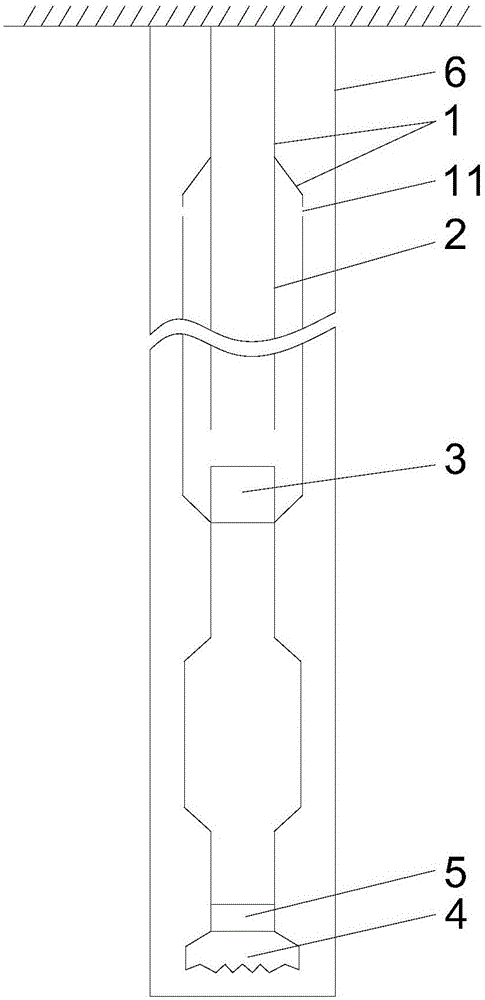
[0035] In order to be able to realize the negative pressure sand cleaning method of gas lift reverse circulation, such as figure 2 As shown, the present invention also provides a gas-lift reverse cycle negative pressure sand cleaning device. The injection outer pipe 1 is provided with the injection inner pipe 2 and the air-water mixer 3 in sequence. The outer wall and the inner wall of the spray outer tube 1 form an annulus space, the side wall of the spray outer tube 1 is provided with a through hole 11, and the through hole 11 provided on the side wall of the spray outer tube 1 is preferably a gas supply And / or the through hole for unidirectional liquid flow can be realized by installing a valve on the through hole. The through hole 11 is higher than the bottom of the spray inner tube 2, and the length of the spray inner tube 2 is smaller than the length of the inner spray tube 2. The length of the spray outer tube 1, the upper part of the spray inner tube 2 is sealed and fi...


PUM


Abstract

The invention relates to a gas life reverse-circulation negative pressure sand-cleaning method and apparatus; the gas life reverse-circulation negative pressure sand-cleaning method comprises the steps of injecting compressed gas into the sand-cleaning apparatus, allowing the compressed gas to expand in the sand-cleaning apparatus, with inner pressure of the sand-cleaning apparatus generates negative pressure relative to inner pressure of a shaft, charging deposited sand in the shaft and borehole fluid into the sand-cleaning apparatus under the action of negative pressure, and discharging from inside of the sand-cleaning apparatus via gas life so that sand cleaning is achieved. The gas life reverse-circulation negative pressure sand-cleaning apparatus comprises an outer spray pipe and an inner spray pipe that are concentric, the inner spray pipe and a gas-water mixer are arranged in the outer spray pipe in sequence, an annular space is formed between the outer wall of the inner spray pipe and the inner wall of the outer spray pipe, the sidewall of the outer spray pipe is provided with through holes, the length of the inner spay pipe is less than that of the outer spray pipe, the gas-water mixer is disposed at the bottom of the inner spray pipe, and the bottom of the outer spray pipe is provided with a drill-grinding structure.

Description

Technical field [0001] The invention belongs to the field of oil and gas well exploitation, and particularly designs a gas lift reverse circulation negative pressure sand cleaning method and a sand cleaning device. Background technique [0002] Sand production in oil and gas wells is a common phenomenon in the process of oil field development. Restoring normal production of oil and gas wells and removing sand from oil and gas wells are essential technical measures. However, when oil and gas wells are producing oil and gas, the debris and mud in the oil and gas layers will be taken out of the formation and into the wellbore. With the continuous progress of oil and gas production, more and more mud and sand will collapse and accumulate underground to block the oil and gas flow passage of the slotted pipe, and the oil and gas production will become less and less, and the pay zone will be buried. And because the pressure in the production wellbore has been reduced for a long time, t...

Claims


Application Information

Patent Timeline
Patent Type & Authority Applications(China)
IPC IPC(8): E21B21/00E21B21/16
Inventor 白彦明李斌王天祥宋中华张强盛勇单全生黎强欧如学张卫贤崔航波张超赵创陆爱华
Owner 库尔勒施得石油技术服务有限公司
Why Eureka
Try Eureka