Crankshaft transmission mechanism of multiple eccentric disc sets

A technology of transmission mechanism and eccentric disc, applied in the direction of transmission, transmission parts, mechanical equipment, etc., can solve the problems of reducing transmission efficiency, difficulty in processing and installation, and high cost of use and maintenance, so as to reduce production difficulty and use cost, The effect of simplifying processing and installation requirements, reducing operating and maintenance costs

Pending Publication Date: 2017-04-26
江苏科选环境科技有限公司
View PDF7 Cites 2 Cited by
  • Summary
  • Abstract
  • Description
  • Claims
  • Application Information

AI Technical Summary

Problems solved by technology

[0003] At present, the crankshaft transmission mechanism in the bounce separator adopts an integrated eccentric wheel crankshaft or a double-bearing splicing type. Specifically, in the crankshaft manufacturing process, there will be the following problems: (1) The processing difficulty and cost are high, which is inconvenient The number of eccentric wheels can be increased or decreased according to the required modularization; (2) The position of the traditional vertical bearing with a seat is relatively fixed during the installation process of the crankshaft, which is not easy to adjust; (3) The traditional sealing ring will increase the rotation resistance, thereby reducing the transmission efficiency, and easy damage, which increases maintenance costs
[0004] The above-mentioned existing eccentric wheel crankshaft has disadvantages such as difficulty in processing and installation, high cost of use and maintenance, complex structure, and inability to modularize and combine

Method used


Image

  • Crankshaft transmission mechanism of multiple eccentric disc sets
  • Crankshaft transmission mechanism of multiple eccentric disc sets
  • Crankshaft transmission mechanism of multiple eccentric disc sets

Examples


Embodiment 1

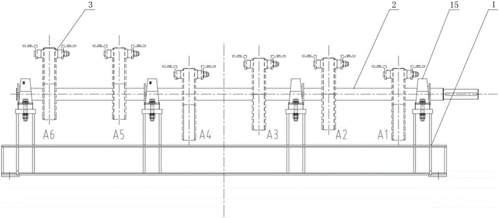
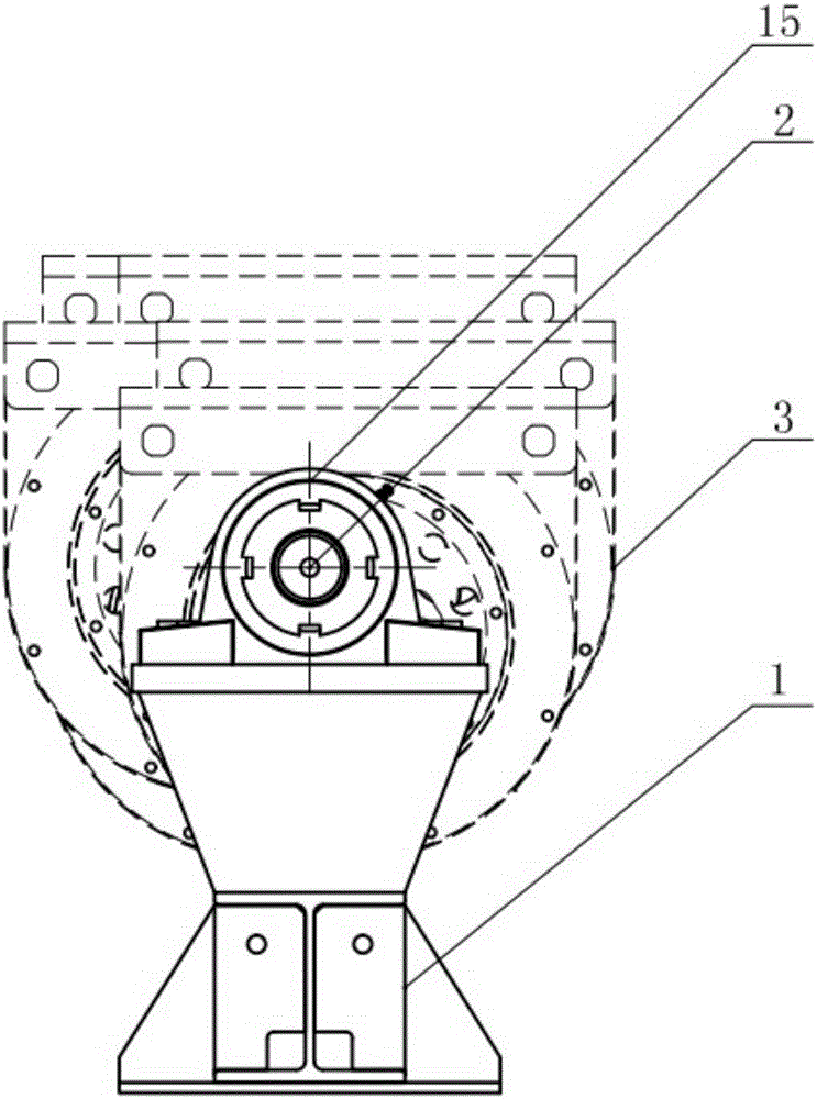
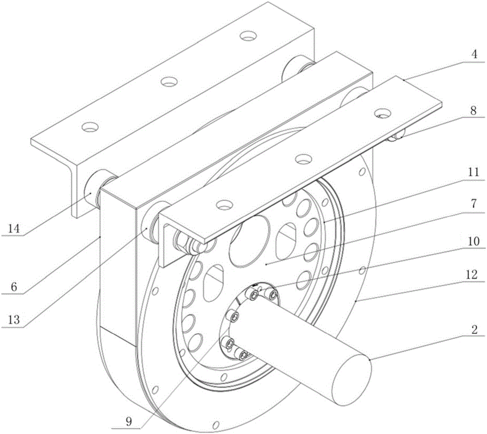
[0024] Embodiment one: see Figure 1~5 As shown, a crankshaft transmission mechanism with multiple eccentric disk groups includes a crankshaft support 1, a shaft 2 and an eccentric disk group 3, and is characterized in that: the shaft 2 is provided with several eccentric disk groups 3, each An eccentric disk group 3 includes an eccentric disk fixing seat 4, a bearing 5, an eccentric disk outer ring 6, an eccentric disk 7 and a sealing device, and the eccentric disk 7 is arranged in the eccentric disk outer ring 6 through the bearing 5, so that The eccentric disk outer ring 6 is fixed on the eccentric disk fixing seat 4 via a pin shaft 8, and the eccentric disk 7 is sealed with the eccentric disk outer ring 6 through the sealing device, and the sealing device adopts a labyrinth seal.

[0025] Such as Figure 2-5 As shown, the eccentric disc 7 is provided with an eccentric shaft hole 9, and the eccentric shaft hole 9 is installed on the shaft 2 through the expansion sleeve 10, ...


PUM


Abstract

The invention discloses a crankshaft transmission mechanism of multiple eccentric disc sets. The crankshaft transmission mechanism comprises a crankshaft support, a shaft and the eccentric disc sets. The crankshaft transmission mechanism is characterized in that the multiple eccentric disc sets are arranged on the shaft, each eccentric disc set comprises an eccentric disc fixing seat, a bearing, an eccentric disc outer ring, an eccentric disc and a sealing device, wherein the eccentric disc is arranged in the eccentric disc outer ring through the bearing, the eccentric disc outer ring is fixed to the eccentric disc fixing seat through a pin shaft, and the eccentric disc and the eccentric disc outer ring are sealed through a sealing device; and labyrinth seal is adopted in the sealing device. According to the crankshaft transmission mechanism, the eccentric disc sets serve as a whole module to be installed on the shaft through an expansion sleeve; in the installation and maintaining process, the crankshaft transmission mechanism is more convenient and flexible; and the number of the eccentric disc sets can be symmetrically increased and decreased in paired according to needs, and therefore the requirement of crankshaft transmission in different bounce sorting machines is met, and the using and maintaining cost is reduced.

Description

technical field [0001] The invention relates to a transmission mechanism used in mechanical equipment such as a bouncing sorter, in particular to a crankshaft transmission mechanism of a multi-width eccentric disc group. Background technique [0002] Garbage sorting technology can choose different methods for different wastes, mainly including: wind separation, magnetic separation, bounce sorting, and density sorting. Among them, the bounce sorting uses the bounce sorter, which is aimed at The conveying equipment with separation function is designed for the separation of inorganic particles in the garbage after coarse crushing. This machine utilizes the characteristics of crushed waste materials, and the conveying sieve plate is designed with a bouncing function to separate heavy, easy-to-roll, light, and flaky materials by bouncing while conveying materials on one side. Movement in the opposite direction to achieve the purpose of sorting. Bounce sorting is mainly to selec...

Claims


Application Information

Patent Timeline
Patent Type & Authority Applications(China)
IPC IPC(8): F16H21/18F16H57/029B07B1/28B07B1/42B07B13/10B07B13/14
CPCF16H21/18F16H57/029B07B1/286B07B1/42B07B13/10B07B13/14
Inventor 瞿海林徐锡锋袁东山陈明
Owner 江苏科选环境科技有限公司
Why Eureka
Try Eureka