Electric connector and assembling method

A technology of electrical connectors and assembly methods, which is applied to the components, connections, and assembly/disassembly of contact pieces of connection devices, which can solve the problem of high-frequency signal transmission distortion, small characteristic impedance between terminals, which is not conducive to ensuring high Frequency signal transmission and other issues, to achieve the effect of increasing the characteristic impedance and convenient assembly method

Inactive Publication Date: 2011-05-04
FOXCONN (KUNSHAN) COMPUTER CONNECTOR CO LTD +1
View PDF0 Cites 1 Cited by
  • Summary
  • Abstract
  • Description
  • Claims
  • Application Information

AI Technical Summary

Problems solved by technology

[0003] In the current electrical connectors, since the terminals must have sufficient width to ensure the strength of the terminals, the facing area between two adjacent terminals is relatively large, which makes the characteristic impedance between the terminals smaller and is not conducive to ensuring high frequency. Signal transmission requirements that distort high-frequency signal transmission

Method used


Image

  • Electric connector and assembling method
  • Electric connector and assembling method
  • Electric connector and assembling method

Examples


Embodiment Construction

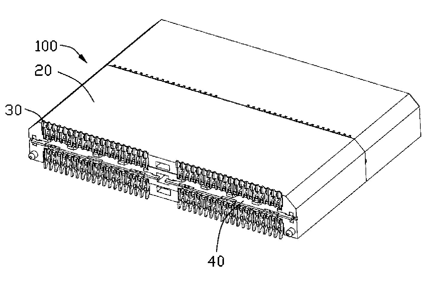
[0029] see Figure 1 to Figure 6 , is the first embodiment of the electrical connector 100 of the present invention.

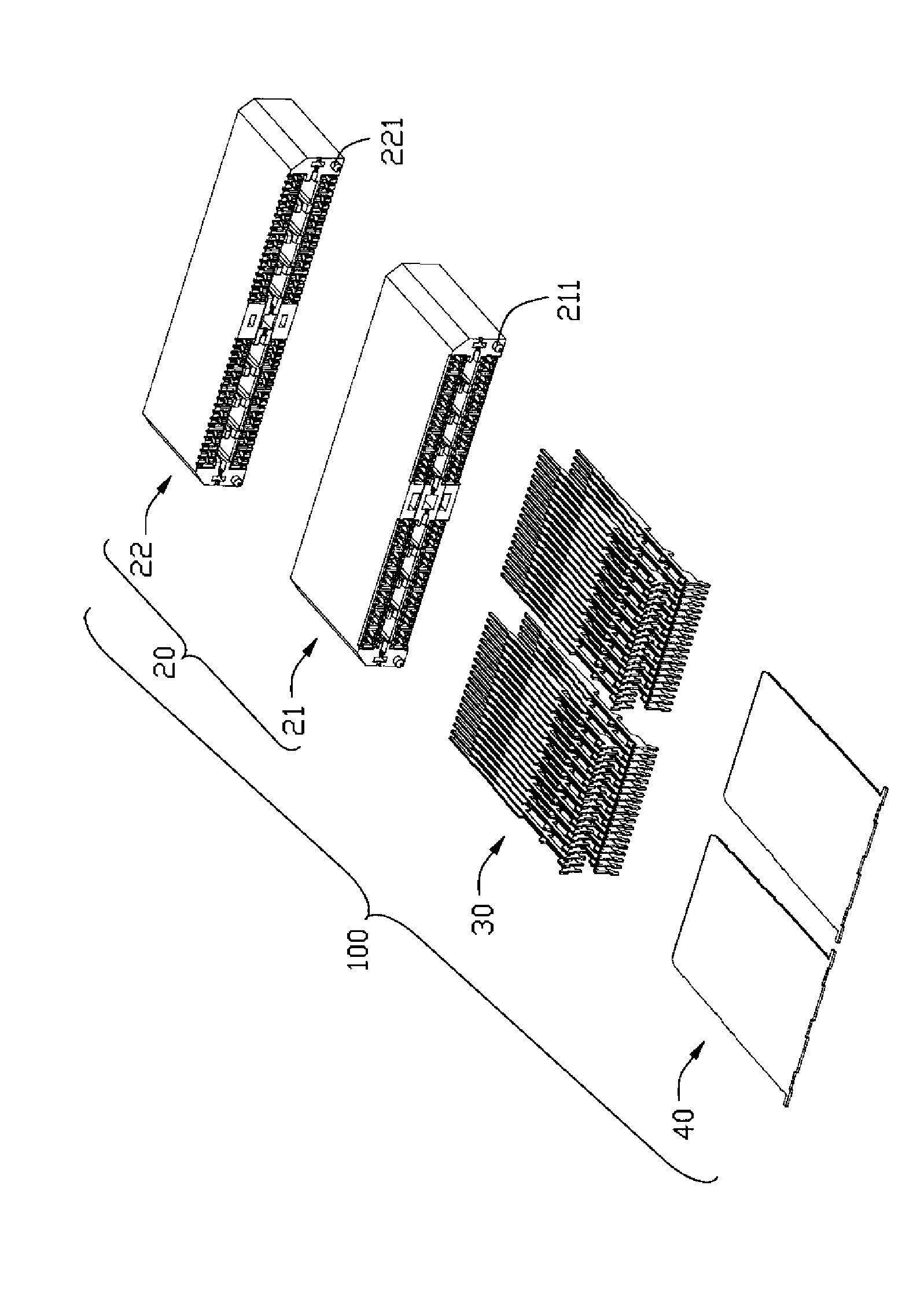
[0030] see figure 1 and figure 2 As shown, the present invention provides an electrical connector 100 mounted on a circuit board (not shown) for connecting with a counterpart (not shown) and achieving electrical contact. The electrical connector 100 includes: an insulating body 20 , a plurality of terminals 30 accommodated in the insulating body 20 , and a metal plate 40 accommodated in the insulating body 20 .

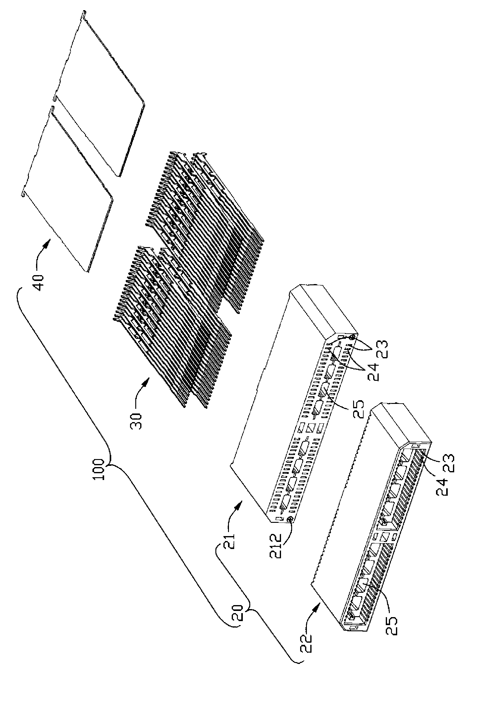
[0031] see figure 2 and image 3 As shown, the insulating body 20 includes a first insulating body 21 mounted on a circuit board (not shown) and a second insulating body 22 stacked on the first insulating body 21 . The first and second insulating bodies 21 and 22 each have first terminal grooves 23 and second terminal grooves 24 alternately accommodating terminals 30 , and first terminal grooves 24 arranged at the bottom of the first and second...


PUM


Abstract

The invention discloses an electric connector. The electric connector comprises an insulating body and a terminal accommodated in the insulating body, wherein a first terminal groove for accommodating a terminal and a second terminal groove for accommodating a terminal are arranged on the insulating body alternately; the terminals are provided with a body part respectively; and each body part is provided with an entity part and an opening. The opening positioned in the first terminal groove is deviated to a first direction relative to the body part; and the opening positioned in the second terminal groove is deviated to a second direction opposite to the first direction relative to the body part. Capacitance is reduced by reducing the facing area, which can cause capacitance effect, between the first terminal and the second terminal, so that the characteristic impedance between the terminals is increased and a high-frequency electrical signal can be stably transmitted.

Description

【Technical field】 [0001] The present invention relates to an electrical connector and its assembly method, especially to an electrical connector with adjacent terminals and its assembly method. 【Background technique】 [0002] In electronic products, electrical connectors are usually used to conduct electrical signals. Generally, electrical connectors have a pair of adjacent signal terminals that transmit high-frequency signals, and a characteristic impedance will be generated between the adjacent signal terminals. Only when appropriate The high-frequency signal transmitted by the signal terminal under the characteristic impedance can be transmitted stably without signal distortion. The characteristic impedance between the terminals decreases as the capacitance between two adjacent terminals increases, and the capacitance is proportional to the facing area of ​​the two terminals. [0003] In the current electrical connectors, since the terminals must have sufficient width to...

Claims


Application Information

Patent Timeline
Patent Type & Authority Applications(China)
IPC IPC(8): H01R13/6461H01R13/02H01R12/71H01R43/20
CPCH01R12/712H01R13/502H01R13/6471H01R13/6474H01R43/20H01R2107/00Y10T29/49208
Inventor 金火星赵建飞
Owner FOXCONN (KUNSHAN) COMPUTER CONNECTOR CO LTD
Why Eureka
Try Eureka