Unlock instant, AI-driven research and patent intelligence for your innovation.

Differential measuring device and method for large-aperture free surface sample surface profile

A surface profile and differential measurement technology, applied in the direction of measuring devices, optical devices, instruments, etc., can solve the problems of easily damaged samples, small measurement range, slow measurement speed, etc., to improve the measurement speed, reduce the measurement cost, improve Effect of measuring range

Inactive Publication Date: 2017-04-26
HARBIN INST OF TECH
View PDF10 Cites 2 Cited by
  • Summary
  • Abstract
  • Description
  • Claims
  • Application Information

AI Technical Summary

Problems solved by technology

[0003] The purpose of the present invention is to solve the problems of slow measurement speed, small measurement range and easy damage to the sample when measuring the surface profile of a large-diameter free-form surface object in the existing method, and to provide a large-diameter free-form surface sample surface profile differential measurement device and method

Method used


Image

  • Differential measuring device and method for large-aperture free surface sample surface profile
  • Differential measuring device and method for large-aperture free surface sample surface profile

Examples


specific Embodiment approach 1

[0025] Specific implementation mode one: combine figure 1 To illustrate this embodiment, a large-diameter free-form surface sample surface profile differential measurement device described in this embodiment includes:

[0026] Illumination module, first detection module and second detection module:

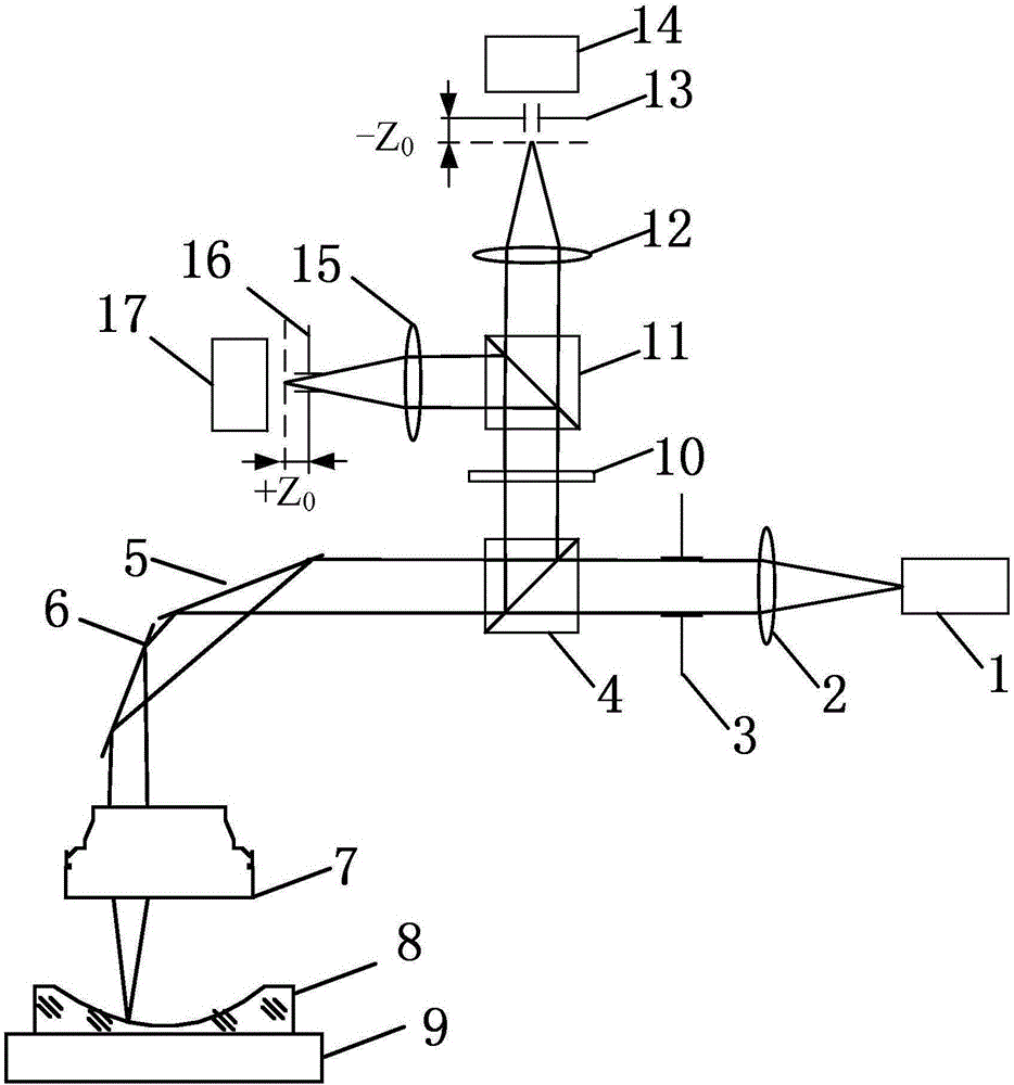
[0027] According to the propagation direction of the illumination light, the lighting modules are as follows: laser 1, collimating mirror 2, aperture 3, PBS-4, high-speed digital scanning galvanometer-5, high-speed digital scanning galvanometer-2 6, scanning lens 7 and three-dimensional Micro displacement stage 9;

[0028] According to the signal light propagation direction, the first detection module is as follows: scanning lens 7, high-speed digital scanning vibrating mirror two 6, high-speed digital scanning vibrating mirror one 5, PBS one 4, optical filter 10, PBS two 11, collecting lens -12, multimode optical fiber -13 and PMT -14;

[0029] According to the direction of si...

specific Embodiment approach 2

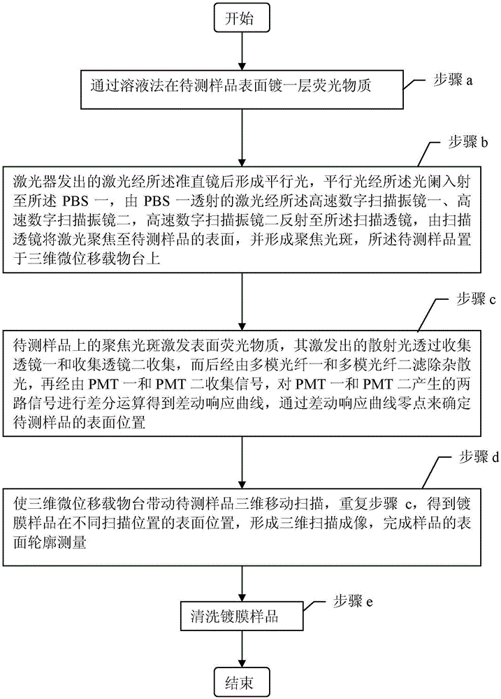
[0040] Specific implementation mode two: combination figure 1 and figure 2 Describe this embodiment, this embodiment is based on a large-diameter free-form surface sample surface profile differential measurement method described in the first embodiment, the method includes the following steps:

[0041] Step a, coating a layer of fluorescent substance on the surface of the sample 8 to be tested;

[0042] Step b, the laser light emitted by the laser 1 passes through the collimating mirror 2 to form parallel light, the parallel light enters the PBS-4 through the aperture 3, and the laser light transmitted by the PBS-4 passes through the high-speed digital scanning oscillator Mirror one 5, high-speed digital scanning vibrating mirror two 6, the high-speed digital scanning vibrating mirror two 6 is reflected to the scanning lens 7, the laser is focused to the surface of the sample 8 to be tested by the scanning lens 7, and a focused spot is formed. The test sample 8 is placed on...


PUM

PropertyMeasurementUnit
Wavelengthaaaaaaaaaa
Optical poweraaaaaaaaaa

Abstract

The invention provides a differential measuring device and method for large-aperture free surface sample surface profile which relate to the large-aperture free surface sample surface profile measuring technology. The purpose of the invention is to solve the problems in the prior art that the measurement speed is slow, the measurement scope is small and the sample is prone to be damaged. The method comprises the following steps: firstly, plating a layer of an organic fluorescent film on the surface of the sample to be measured. The laser light emitted from the laser sequentially passes a collimating lens and a diaphragm to become parallel light; then through PBS transmission, high-speed digital scanning galvanometer and scanning lens transmission, focused light spots are formed on the sample to make the surface of the sample radiate fluorescence; the fluorescence is collected by two PMTs. Differential operations conducted to the signals generated from the two PMTs to obtain a differential axial response curve. According to the curve, the sample surface position is determined so that the sample is moved in three dimensions. With the same method, the surface position of the sample at different positions can be obtained and thus the measurement is completed. The invention is suitable for the measurement of large-aperture free surface sample surface profile.

Description

technical field [0001] The invention relates to a technique for measuring the surface topography of a large-diameter free-form surface sample by using a scanning lens as an illumination and imaging lens. Background technique [0002] As free-form surface parts are more and more widely used in modern industry, the precision machining and manufacturing industry has higher and higher requirements for measurement accuracy, and the surface profile measurement of large-diameter free-form surface objects has received more and more attention. Most of these samples adopt two types of detection methods, one is the detection method of aspheric optical components, and the other is the contact measurement. However, for these two methods, the former is not easy to measure samples with more degrees of freedom and larger sizes, while the latter has slow measurement speed, small measurement range and easy damage to samples. Contents of the invention [0003] The purpose of the present inv...

Claims


Application Information

Patent Timeline
IPC IPC(8): G01B11/24
CPCG01B11/24
Inventor 刘俭刘辰光谭久彬刘妍
Owner HARBIN INST OF TECH
Features
  • R&D
  • Intellectual Property
  • Life Sciences
  • Materials
  • Tech Scout
  • Unparalleled Data Quality
  • Higher Quality Content
  • 60% Fewer Hallucinations
Learn More