Mapping system based on laser navigation substation patrol robot as well as method

An inspection robot and laser navigation technology, applied in the field of mapping systems, can solve the problems of time-consuming data collection, large cumulative errors in substation maps, and high costs, and achieve the effects of reducing manpower consumption, eliminating cumulative errors, and improving accuracy

Active Publication Date: 2017-04-26
STATE GRID INTELLIGENCE TECH CO LTD
View PDF7 Cites 16 Cited by
  • Summary
  • Abstract
  • Description
  • Claims
  • Application Information

AI Technical Summary

Problems solved by technology

[0004] 1. Most substation construction maps are now manually drawn, and manual surveying and mapping is performed through total stations, meter rulers and laser rangefinders; however, manual drawing will produce large errors, which will affect the positioning accuracy and navigation of laser navigation substation inspection robots. The effect has an impact, and manual drawing will also consume a lot of manpower and time costs;
[0005] 2. Use the laser radar and encoder installed on the laser navigation substation inspection robot body to collect data together, and then fuse the data later to generate a substation map. The substation map generated in this way will produce a large cumulative error, resulting in some The ring road cannot be closed;
[0006] 3. Use 3D mapping equipment to set up multiple points in the substation for scanning and mapping. Later, the 3D map will be spliced ​​with the data scanned by the station through software, and then the 3D map needs to be converted into the 2D required by the laser navigation substation inspection robot. For substation maps, it is necessary to purchase special equipment for 3D mapping, which is expensive and needs to be mapped in small areas at intervals. In the later stage, the maps need to be stitched together through software, which takes a lot of time to collect data.

Method used


Image

  • Mapping system based on laser navigation substation patrol robot as well as method
  • Mapping system based on laser navigation substation patrol robot as well as method
  • Mapping system based on laser navigation substation patrol robot as well as method

Examples


Embodiment Construction

[0036] The present invention will be further described below in conjunction with the accompanying drawings and embodiments.

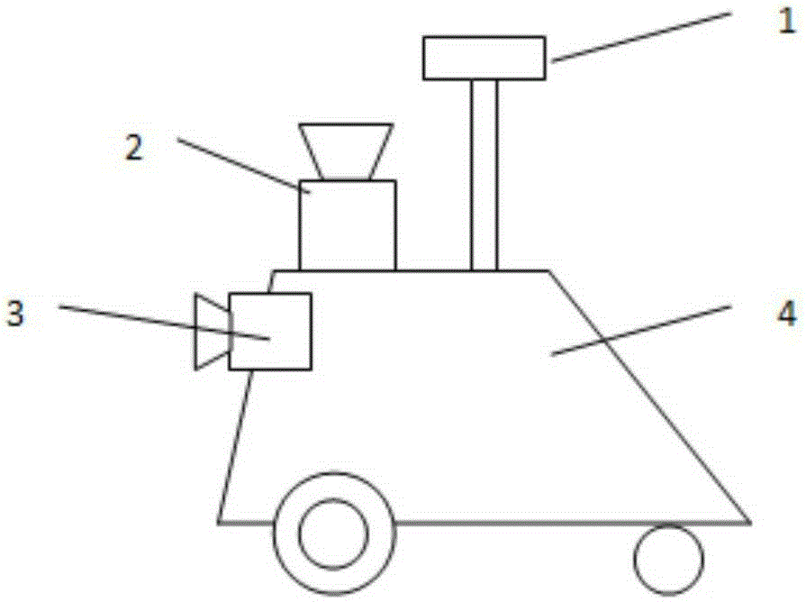
[0037] Such as figure 1 As shown, the substation mapping method of laser navigation substation inspection robot's GPS, vision and laser radar, which includes a substation inspection robot equipped with laser radar, the robot is equipped with industrial computer, GPS module, vision module and laser radar .

[0038] The substation inspection robot equipped with laser radar has the function of remote control driving.

[0039] The GPS module is linked with the industrial computer through the RS232 interface.

[0040] The vision module and laser radar are connected with the industrial computer through the LAN interface.

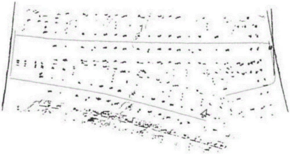
[0041] When the substation inspection robot using laser navigation is building a map, the laser navigation substation inspection robot needs to drive in the required mapping area. At this time, GPS, vision module and laser radar will col...


PUM


Abstract

The invention discloses a mapping system based on a laser navigation substation patrol robot as well as a method. The mapping system comprises a laser radar, an industrial personal computer, a GPS module and a vision module, wherein the laser radar and the GPS module are arranged on a patrol robot body; the vision module is arranged at the front end of the patrol robot body; the industrial personal computer acquires environment screenshots of the vision module, compares two adjacent images and analyzes the course angle of the robot; the laser radar transmits acquired distance information to the industrial personal computer, the GPS module transmits acquired coordinates information to the industrial personal computer, and the industrial personal computer transforms the distance information into a two-dimensional plane picture and rotates the plane picture to the same course angle as the robot so as to acquire the map of the current perimeter zone of the robot. With adoption of the mapping method for the substation on the basis of GPS, vision and laser radar of the laser navigation substation patrol robot, defects of the conventional substation mapping method can be overcome, the mapping precision can be improved, the mapping speed can be increased, and labor consumption can be reduced.

Description

technical field [0001] The invention relates to a mapping system and method based on a laser navigation substation inspection robot. Background technique [0002] Substation mapping is a necessary link before the operation of the laser navigation substation inspection robot. It mainly records the map of the substation in the form of data as detailed and accurate as possible. The laser navigation substation inspection robot uses the map to compare with the surrounding information obtained by the laser radar in real time, and determines the position of the laser navigation substation inspection robot through a positioning algorithm. Therefore, the accuracy of the built substation map is very important for the navigation and positioning of the laser navigation substation inspection robot. [0003] Existing substation mapping methods include: [0004] 1. Most substation construction maps are now manually drawn, and manual surveying and mapping is performed through total statio...

Claims


Application Information

Patent Timeline
Patent Type & Authority Applications(China)
IPC IPC(8): G01C21/00
Inventor 孔令文田晓璐刘加科秦振华孙凯付崇光孙志周
Owner STATE GRID INTELLIGENCE TECH CO LTD
Why Eureka
Try Eureka