Core X-ray scanning testing experimental method

An experimental method and scanning testing technology, which are applied in the field of X-ray scanning testing of cores, can solve the problems of bulky instruments, high radiation intensity, and great harm to human body, and achieve simple device structure, overcome ray hardening, and reduce harm to human body. Effect

Inactive Publication Date: 2017-04-26
CHINA NAT OFFSHORE OIL CORP +2
View PDF5 Cites 11 Cited by
  • Summary
  • Abstract
  • Description
  • Claims
  • Application Information

AI Technical Summary

Problems solved by technology

[0011] Disadvantages of the three-generation scanning method of object rotation: (1) This experimental method is mainly used to determine the pore structure of short cores, not mainly used for oil-water saturation distribution in the process of core water flooding
(2) When used in core water flooding experiments, it can only measure the oil-bearing water saturation distribution of shorter cores, and cannot measure the water-bearing oil saturation distribution of long cores during water flooding
(3) The core needs to be rotated during the measurement process, so that the fluid in the core is subjected to external forces, which does not conform to the actual situation in the process of core water flooding
[0013] The disadvantages of using a medical CT machine for core analysis are: (1) The software on the medical CT machine is compiled for different parts of the human body, and the obtained image projection data will cause ray beam hardening, so accurate quantitative testing accuracy is not enough
(2) The cost of experimental equipment is too high, and ordinary companies and colleges cannot afford it. The device is large in size and complex in structure
(3) The ray radiation intensity generated during the operation of the instrument is relatively high, which is very harmful to the human body
[0016] The disadvantage of this device is that the cost is high and the instrument is bulky

Method used


Image

  • Core X-ray scanning testing experimental method
  • Core X-ray scanning testing experimental method
  • Core X-ray scanning testing experimental method

Examples


Embodiment Construction

[0045] In order to better understand the above-mentioned technical solution, the above-mentioned technical solution will be described in detail below in conjunction with the accompanying drawings and specific implementation methods.

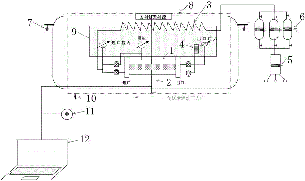
[0046] Such as Figure 2 ~ Figure 3 As shown, a kind of rock core X-ray scanning test experimental method described in the present embodiment comprises the following steps:

[0047] S1. Saturated formation water: install the core holder 1 on the conveyor belt, connect the pipeline, use the displacement pump 5 to apply confining pressure to the core holder through the intermediate container 6, and after the confining pressure is loaded, the core holder 1 and The pipeline is evacuated to saturate the formation water. After the saturation of the formation water is completed, the one-button push switch 11 is pressed, and the core holder 1 moves with the conveyor belt. After the core holder 1 enters the X-ray emitting and receiving device 8, the detec...


PUM


Abstract

The invention provides a core X-ray scanning testing experimental method. The method includes steps of S1, saturated formation water; S2, after the saturated formation water is full, starting a displacement pump to fill oil in the core, and displacing until there is no water flow completely, wherein the state at the moment is irreducible water state; S3, primary scanning; S4, properly prolonging the time interval of recording and scanning at the later period of the experiment until there is no oil discharged through displacement of oil by water, finishing the experiment; S5, for the X-ray intensity value obtained by scanning is related to the variety and quantity of the saturated liquid in the core, calculating the water-containing and oil-containing saturation value of a rock section at different moments by using the X-ray intensity value; thus the long core can be scanned, and the cost is largely reduced; besides, the method is less harmful to human body, and able to easily realize the purpose of analyzing the oil-containing and water-containing saturation degree by the core X-ray scanning.

Description

technical field [0001] The invention relates to the technical field of rock core water flooding oil detection, in particular to an experimental method for rock core X-ray scanning testing. Background technique [0002] X-ray scanning technology can observe the internal structure and liquid flow distribution of the whole core in a short period of time without changing the external shape and internal structure of the core. [0003] The principle of X-ray scanning imaging technology is based on the BEERS theorem. When a beam of X-rays penetrates an object, part of the X-rays will be absorbed or reflected, but most of them can penetrate the object. The intensity of X-rays passing through an object is related to the density of the object, so the X-ray intensity detected by the detector and the thickness of the object satisfy the formula [0004] [0005] In the formula, I 0 is the original X-ray intensity, I is the X-ray intensity through the object, μ is the X-ray depletion...

Claims


Application Information

Patent Timeline
Patent Type & Authority Applications(China)
IPC IPC(8): G01N23/04G01N1/28
CPCG01N23/04G01N1/28G01N23/046
Inventor 雷霄王智琦杨朝强张辉何胜林孙雷刘双琪陈一健
Owner CHINA NAT OFFSHORE OIL CORP
Why Eureka
Try Eureka