Optical fiber splice closure with differential micro-bending inductor
A fiber optic cable connection and sensor technology, applied in the field of information and communication, can solve the problem that the OTDR fiber optic cable test distance and the actual geographic distance cannot be quickly and accurately matched, and achieve high commercial promotion value, improve repair efficiency, and simple operation.
- Summary
- Abstract
- Description
- Claims
- Application Information
AI Technical Summary
Problems solved by technology
Method used
Image
Examples
example 1
[0027] Example 1 (comparative example)
[0028] Use OTDR to measure the distance of the ordinary splice box optical cable. The operation sequence and average time consumption: Step 1, disassemble the splice box, which takes 5 minutes; Step 2, cut the optical fiber, and use OTDR to test the breakpoint distance; Step 3, Splice and restore the cut It takes 10 minutes to open the optical fiber; step 4, reassemble the splice box, it takes 10 minutes; a total of 30 minutes.
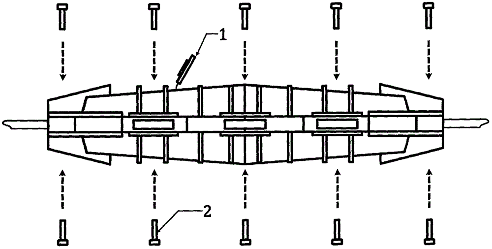
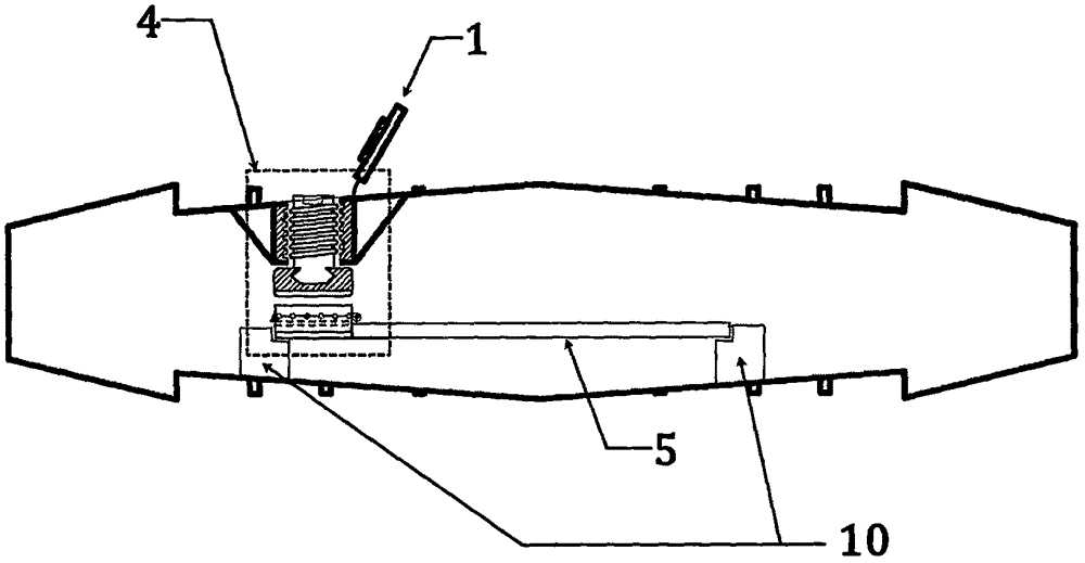
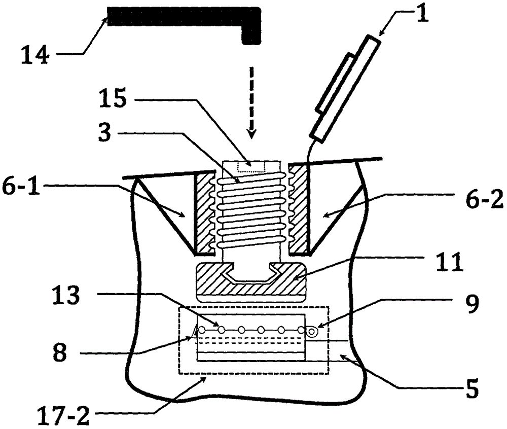
[0029] Use OTDR to measure the distance of the splice box optical cable of the present invention. Operation sequence and time-consuming average: Step 1. Use the hexagonal wrench 14 to twist the rotating bolt 3 to a suitable position, causing optical power attenuation, which takes 2 minutes; then the OTDR real-time test is new The distance of the gain and loss points is the distance of the optical cable of this splice box; step 2, restore the rotating bolt 3 to the initial position, and it takes 2 minutes;
[0...
example 2
[0031] Example 2 (comparative example)
[0032] The distance between Mianyang and Bandong Bridge is 42Km, and the buried 72-core long-distance optical cable is 45.62Km. There are 20 ordinary splice boxes connected in series in the optical cable line, and the distance between adjacent splice boxes is 0.1Km to 5Km. The technical information of the line is relatively complete, but due to repeated maintenance , replaced 3 sections of optical cables with different lengths, resulting in some inaccurate technical information.
[0033] Emergency repair process: After receiving a report from the network management center, the optical cable was partially interrupted at 23.85Km after OTDR testing in the computer room in Mianyang. The emergency repair team came to the splice box A according to the technical data. The technical data showed that the distance of the optical cable should be 23.65Km. The splice box was disassembled, and the 1-core optical fiber was cut to end. The Mianyang com...
example 3
[0035] The distance between Mianyang and Rainbow Bridge is 40Km, and the buried 72-core long-distance optical cable is 42.73Km. There are 21 splice boxes connected in series in the cable line, of which 6 fibers are set for random inspection. The distance between adjacent splice boxes is 0.1Km to 5Km. The technical information of the line is relatively vague.
[0036] Emergency repair process: After receiving a report from the network management center, the optical cable was partially interrupted at 21.25Km after OTDR testing in the computer room in Mianyang. The emergency repair team came to the connection box A of the present invention based on previous experience, twisted the rotary switch 15 of the connection box A of the present invention, and the Mianyang computer room reported that its OTDR test data was lost in real time at 20.23Km, and after the connection box was restored, it was 0.8Km and then another A connection box B, twist its rotary switch 15, Mianyang computer r...
PUM
 Abstract
Description
Claims
Application Information
 - R&D
- Intellectual Property
- Life Sciences
- Materials
- Tech Scout
- Unparalleled Data Quality
- Higher Quality Content
- 60% Fewer Hallucinations
Browse by: Latest US Patents, China's latest patents, Technical Efficacy Thesaurus, Application Domain, Technology Topic, Popular Technical Reports.
© 2025 PatSnap. All rights reserved.Legal|Privacy policy|Modern Slavery Act Transparency Statement|Sitemap|About US| Contact US: help@patsnap.com


