Combinational design method for radial and circumferential stiffening ribs of flange joints of tower feet of steel tube tower

A flange joint and combined design technology, applied in design optimization/simulation, calculation, special data processing applications, etc., can solve problems such as less than yield stress and failure to exert steel strength, so as to improve ultimate bearing capacity and uniform force degree, the effect of reducing the degree of stress concentration

Active Publication Date: 2017-04-26
STATE GRID FUJIAN ELECTRIC POWER CO LTD +3
View PDF4 Cites 6 Cited by
  • Summary
  • Abstract
  • Description
  • Claims
  • Application Information

AI Technical Summary

Problems solved by technology

However, there are the following deficiencies in the design and application of the above-mentioned tower foot stiffener flange: the simplified stiffened flange bottom plate is approximately considered as a rectangle, but the actual calculation unit of the stiffened flange bottom plate is a fan-shaped area; when the local area of ​​the flange bottom plate exceeds the yield stress of the steel , the stress value of most of its areas is still far less than the yield stress, and it is still in an elastic state, that is, the bearing capacity of the flange is controlled by a small part of the area that first exceeds the yield stress of the steel, and most of the other areas do not exert the strength of the steel.

Method used


Image

  • Combinational design method for radial and circumferential stiffening ribs of flange joints of tower feet of steel tube tower
  • Combinational design method for radial and circumferential stiffening ribs of flange joints of tower feet of steel tube tower
  • Combinational design method for radial and circumferential stiffening ribs of flange joints of tower feet of steel tube tower

Examples


Embodiment Construction

[0030] Best practice:

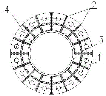
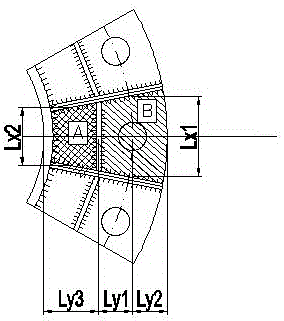
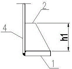
[0031] Refer to attached figure 2 And attached image 3 , a steel pipe tower (rod) tower foot radial and circumferential combined stiffener flange joint, the radial and circumferential combined stiffener flange joint includes a flange bottom plate 1 for connection, a radial stiffener 2. Circumferential stiffeners 3; the flange bottom plate 1 is an annular steel plate welded with the steel pipe 4. The radial stiffener 2 is a stiffener from the center of the steel pipe to the steel pipe wall; the circumferential stiffener 3 is a stiffener parallel to the cutting surface of the outer peripheral surface of the steel pipe; the circumferential stiffener 3 is vertical The radial stiffener 2 is connected with the weld seam; the bottom of the circumferential stiffener 3 is welded with the flange bottom plate 1; the radial stiffener 2 is vertically connected with the steel pipe wall Weld seam connection, the bottom is welded seam connection with the flange bo...


PUM


Abstract

The invention relates to a construction design method for flanged connections of steel tube towers or steel pipe poles applied in electric transmission lines, in particular to a combinational design method for radial and circumferential stiffening ribs of flange joints of tower feet of a steel tube tower. The method comprises following steps: adding circumferential stiffening ribs on original flange joints and designing original radial stiffening ribs in a combinational mode; taking a fan shape enclosed by the radial and circumferential stiffening ribs as a calculation unit and taking the ratio of limit value and design value borne by a flange bottom plate as references to adjust configurations of all parameters of flange joints with finite element analysis as a calculation basis; finally obtaining new flange joint construction. The combinational design method for radial and circumferential stiffening ribs of flange joints of tower feet of the steel tube tower has following beneficial effects: the overall calculation is largely close to actual value; stress concentration degree of the flange bottom plate is reduced to the maximum; uniform stress degree is increased; extreme bearing capabilities of flange joints are greatly improved; and strength of all regions of steel material is effectively applied.

Description

technical field [0001] The invention relates to a method for designing a flange connection structure of a steel pipe tower or a steel pipe pole of a power transmission line, in particular to a design method for combining radial and circumferential stiffeners on a flange node at the foot of a steel pipe tower. Background technique [0002] In the prior art, the commonly used stiffener flanges at the foot of the steel pipe tower (rod) of the transmission line adopt a flange bottom plate and a radial stiffener. The vertical weld of the radial stiffener is welded with the steel pipe wall, and the transverse weld of the radial stiffener is welded with the flange bottom plate. figure 1 shown. This kind of stiffening flange has the characteristics of high overall rigidity and high bearing capacity, so it is widely used in steel pipe towers (rods) of transmission lines. [0003] The calculation of the bearing capacity of the above-mentioned stiffening flange is mainly based on the...

Claims


Application Information

Patent Timeline
Patent Type & Authority Applications(China)
IPC IPC(8): G06F17/50
CPCG06F30/17G06F30/23
Inventor 唐自强纪炳章翁兰溪刘志伟池金明黄晓予李宏进刘许凡
Owner STATE GRID FUJIAN ELECTRIC POWER CO LTD
Why Eureka
Try Eureka