Optical layer decomposition method based on spatial transformation model

A space transformation and layer decomposition technology, applied in image data processing, 2D image generation, instruments, etc., can solve the problems of poor decomposition effect and low efficiency, and achieve the effect of improving computing efficiency and layer decomposition effect

Active Publication Date: 2017-04-26
XIDIAN UNIV
View PDF1 Cites 1 Cited by
  • Summary
  • Abstract
  • Description
  • Claims
  • Application Information

AI Technical Summary

Problems solved by technology

[0018] The purpose of the present invention is to overcome the defects in the above-mentioned existing unsupervised single-sheet mixed image decomposition method, and propose an optical layer decomposition method based on a spatial transformati...

Method used


Image

  • Optical layer decomposition method based on spatial transformation model
  • Optical layer decomposition method based on spatial transformation model
  • Optical layer decomposition method based on spatial transformation model

Examples


Embodiment Construction

[0043] Below in conjunction with accompanying drawing and specific embodiment, the present invention is described in further detail:

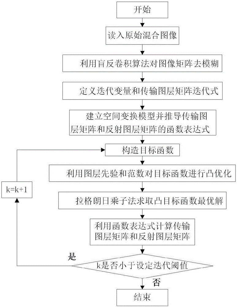
[0044] refer to figure 2 , the present invention comprises the following steps:

[0045] Step 1, read in the original mixed image to obtain an image matrix I, in which multiple information of transmission and reflection are mixed.

[0046] Step 2, deconvolution is the basic method to restore the blurred image. If the blur function of the imaging system is known, deblurring is a conventional deconvolution problem. Blind deconvolution algorithms are required if there is no or little prior knowledge about the mixture of transmission and reflection layers. The image matrix I is deblurred using the blind deconvolution algorithm to obtain the initial transmission layer matrix The algorithm can realize the blind separation of different layers in the mixed image on the basis of maintaining the complex structure of the mixed image and the clear edg...


PUM


Abstract

The invention provides an optical layer decomposition method based on a spatial transformation model, aiming to solve the technical problems of bad decomposition effect and low efficiency in a conventional non-supervision single mixed image decomposition method. The realization steps include reading in an original mixed image; fuzzing by means of a blind deconvolution algorithm; defining iterative variables and a transmission layer matrix iteration formula; creating a spatial transformation model and deriving the function expression of the transmission layer matrix and the reflection layer matrix; constructing target functions, adding constraint conditions by means of layer prior, performing regularization with L1 norms, and realizing the target function convex optimization; solving the optimal solution of convex target function by means of a Lagrangian multiplier method; calculating the transmission layer matrix and the reflection layer matrix by means of the function expression; and determining whether the iteration frequency is greater than the set threshold, if yes, the iteration is completed, otherwise, the convex target function is updated. The optical layer decomposition method improves the decomposition effect of the mixed image and improves the calculating efficiency.

Description

technical field [0001] The invention belongs to the technical field of machine vision and image processing, and relates to an optical layer decomposition method, in particular to an optical layer decomposition method based on a space transformation model, which can be used for target positioning and image feature extraction. Background technique [0002] In real life, when light propagates in a quasi-transparent medium, multiple reflections and refractions will occur. Common quasi-transparent media include glass of different shapes, transparent films of different materials, etc., so that imaging equipment or human eyes can see through the quasi-transparent medium. The observed scene always includes the scene behind the transparent medium, that is, the transmission layer, and the scene before the transparent medium, that is, the reflection layer. The formed image contains information of both layers at the same time, called Blend images. The overlapping part of the two layers...

Claims


Application Information

Patent Timeline
IPC IPC(8): G06T11/00
CPCG06T11/00
Inventor 曹芙蓉吴鑫杨琛黄曦孙浩
Owner XIDIAN UNIV
Why Eureka
Try Eureka