
Button battery and manufacturing method therefor

A technology for button batteries and manufacturing methods, which is applied in secondary battery manufacturing, batteries, lithium storage batteries, etc., can solve the problems of high internal resistance of batteries, poor rate discharge, and direction error of battery cell height, etc., so as to prevent short-circuit hidden dangers, internal The effect of reduced resistance and strong discharge capacity of large current

Active Publication Date: 2017-04-26
CHONGQING VDL ELECTRONICS
View PDF6 Cites 27 Cited by
  • Summary
  • Abstract
  • Description
  • Claims
  • Application Information

AI Technical Summary

Problems solved by technology

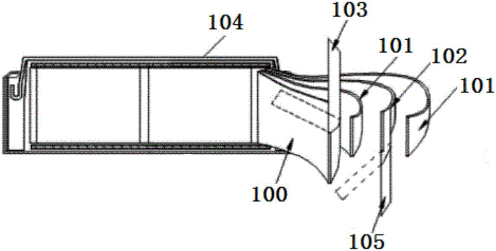
However, at present, the batteries of button batteries are mostly made by winding (such as figure 1 As shown), that is, the positive electrode sheet 100, the separator 101, and the negative electrode sheet 102 are wound together, because the dislocation of the winding must exist, and then there is a certain error in the height direction of the battery cell formed by winding; At the same time, since the positive electrode sheet 100 is only connected to the housing 104 through one positive tab 103, and the negative electrode sheet 102 is only connected to the housing 104 through one negative tab 105, the battery has high internal resistance, poor rate discharge and easy short circuit. and other shortcomings

Method used


Image

  • Button battery and manufacturing method therefor
  • Button battery and manufacturing method therefor
  • Button battery and manufacturing method therefor

Examples


Embodiment Construction

[0036] In the following, only some exemplary embodiments are briefly described. As those skilled in the art would realize, the described embodiments may be modified in various different ways, all without departing from the spirit or scope of the present invention. Accordingly, the drawings and descriptions are to be regarded as illustrative in nature and not restrictive.

[0037] In the description of the present invention, unless otherwise specified, the meaning of "plurality" is two or more; the term "upper, lower, left, right, inner, outer, front end, rear end, head, tail" The orientation or positional relationship indicated by etc. is based on the orientation or positional relationship shown in the drawings, and is only for the convenience of describing the simplified description of the present invention, rather than indicating or implying that the referred device or element must have a specific Azimuth configuration and operation, therefore, should not be construed as li...


PUM

PropertyMeasurementUnit
thicknessaaaaaaaaaa

Abstract

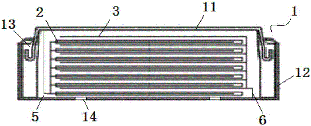
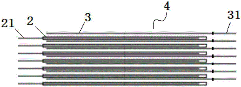
The invention relates to a button battery and a manufacturing method therefor. The button battery comprises a shell, wherein a plurality of positive electrode plates and negative electrode plates are arranged in the shell; each positive electrode plates and each negative electrode plate are laminated to form a columnar cell; each positive electrode plates and each negative electrode plate are connected with the shell through a current collector separately; the manufacturing method for the button battery comprises the steps of coating each positive electrode plates and each negative electrode plate with an active material separately, and enabling a first current collector, connected with each positive electrode plate, to be connected with the shell through an aluminum foil; enabling a second current collector, connected with each negative electrode plate, to be connected with the shell through a copper foil; and sleeving the columnar cell with a sealing ring, and performing baking on the columnar cell, and then carrying out electrolyte injection, sealing, formation and capacity grading. The button battery adopts multiple positive electrode plates and negative electrode plates, and each positive electrode plates and each negative electrode plate are provided with tabs respectively, so that the internal resistance of the battery is reduced while the high-current discharging capability is high due to that the multiple tabs are adopted for flow guiding; and in addition, the positive electrode plates and the negative electrode plates are laminated alternately at intervals, so that the height of the battery is adjustable.

Description

technical field [0001] The invention belongs to the technical field of batteries, in particular to a button battery and a manufacturing method thereof. Background technique [0002] With the development of economy and progress of society, people's life is becoming more and more intelligent and convenient. The emergence of various electronic devices has reduced people's labor, making it more effective with less effort. Among them, the battery of the electronic device is one of the essential configurations for the battery life of the electronic device. [0003] The button battery is an all-metal shell sealed battery, which is characterized by small battery size, strong sealing, and low battery discharge current. Therefore, it is widely used in computers, hearing aids, electronic watches, radios and various electronic gadgets. However, at present, the batteries of button batteries are mostly made by winding (such as figure 1 As shown), that is, the positive electrode sheet ...

Claims


Application Information

Patent Timeline
Patent Type & Authority Applications(China)
IPC IPC(8): H01M2/12H01M2/26H01M10/0525H01M10/0583H01M50/159H01M50/184H01M50/186H01M50/528H01M50/54
CPCH01M10/0525H01M10/0583H01M50/375H01M50/186H01M50/54H01M50/159H01M50/184H01M10/0427Y02E60/10H01M50/109H01M50/342Y02P70/50H01M2004/025H01M10/052H01M50/183H01M50/155H01M50/538H01M2200/10
Inventor 朱传钦周显茂
Owner CHONGQING VDL ELECTRONICS
Learn More