Cascaded voltage lifting quasi-Z source converter

A converter and voltage technology, which is applied in the field of cascaded voltage-lift quasi-Z source converters, can solve the problems of inability to achieve a large range, non-common ground, boost, etc., and achieve the effect of wide application prospects and continuous current

Inactive Publication Date: 2017-04-26
SOUTH CHINA UNIV OF TECH
View PDF2 Cites 3 Cited by
  • Summary
  • Abstract
  • Description
  • Claims
  • Application Information

AI Technical Summary

Problems solved by technology

However, the traditional DC/DC boost converter is limited by the duty cycle, heat generation and loss, and cannot achieve a large boost. For example, the Boost converter has a voltage gain of 1/(1-D), where D is the duty cycle Duty cycle, when the duty cycle is close to 1, a higher voltage gain can be obtained, but at the same time, the above-mentioned problems will be encountered; in a

Method used


Image

  • Cascaded voltage lifting quasi-Z source converter
  • Cascaded voltage lifting quasi-Z source converter
  • Cascaded voltage lifting quasi-Z source converter

Examples


Example Embodiment

[0011] In order to further illustrate the content and characteristics of the present invention, the specific embodiments of the present invention will be described in detail below with reference to the accompanying drawings, but the implementation of the present invention is not limited thereto.

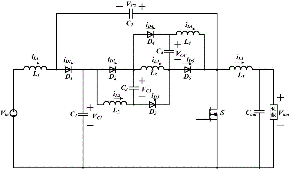
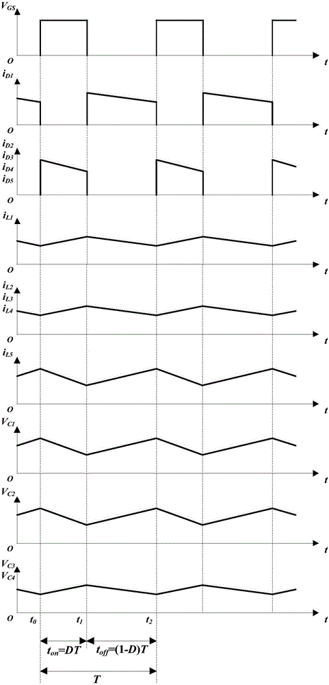
[0012] As an example, the basic topology of the cascaded voltage-lift quasi-Z source converter and the reference direction of the voltage and current of each main component are as follows: figure 1 Shown. For the convenience of analysis, the devices in the circuit structure are regarded as ideal devices. The drive signal V of the switch tube S GS , The first diode D 1 Current i D1 , The second diode D 2 Current i D2 , The third diode D 3 Current i D3 , The fourth diode D 4 Current i D4 , The fifth diode D 5 Current i D5 , The first inductor L 1 Current i L1 , The second inductor L 2 Current i L2 , The third inductor L 3 Current i L3 , The fourth inductor L 4 Current i L4 , The fifth in...


PUM


Abstract

The invention provides a cascaded voltage lifting quasi-Z source converter including a DC input power supply Vin, a first inductor (L1), a first diode (D1), a first capacitor (C1), a second capacitor (C3), a second diode (D2), a second inductor (L2), a third inductor (L3), a third capacitor (C3), a third diode (D3), a fourth diode (D4), a fourth capacitor (C4), a fourth inductor (L4), a fifth diode (D5), a fifth inductor (L5), a switch (S), an output capacitor (Cout), and a load. The cascaded voltage lifting quasi-Z source converter has a high voltage gain compared with a Boost converter and a conventional quasi-Z-source converter, and is suitable for the cases of non-isolated high-gain DC voltage conversion.

Description

technical field [0001] The invention relates to the field of DC / DC converters, in particular to a cascaded voltage lift type quasi-Z source converter. Background technique [0002] In renewable energy power generation systems, such as photovoltaic power generation and fuel cell systems, DC / DC converters are required to have high voltage gain and small input current ripple to facilitate integration into the AC grid and protect input and output. However, the traditional DC / DC boost converter is limited by the duty cycle, heat generation and loss, and cannot achieve a large boost. For example, the Boost converter has a voltage gain of 1 / (1-D), where D is the duty cycle Duty cycle, when the duty cycle is close to 1, a higher voltage gain can be obtained, but at the same time, the above-mentioned problems will be encountered; in addition, many DC / DC converters based on Z sources and quasi-Z sources, although using impedance The source network has achieved a boost, but there is s...

Claims


Application Information

Patent Timeline
IPC IPC(8): H02M3/156H02M3/07
CPCH02M3/156H02M3/07
Inventor 张波沈瀚云丘东元肖文勋
Owner SOUTH CHINA UNIV OF TECH
Why Eureka
Try Eureka