A parallel multi-input coupled inductor buck-boost converter

A buck-boost converter, coupled inductance technology, applied in the direction of conversion equipment without intermediate conversion to AC, can solve the problem that multiple input sources and load power conversion cannot be realized at the same time, and it is not suitable for low-voltage and high-current applications. Problems such as intermittent current at the output end, to achieve the effect of reducing the number, improving the dynamic performance, and increasing the control strategy

Inactive Publication Date: 2016-04-27
NANJING UNIV OF AERONAUTICS & ASTRONAUTICS
View PDF5 Cites 0 Cited by
  • Summary
  • Abstract
  • Description
  • Claims
  • Application Information

AI Technical Summary

Problems solved by technology

Literature "Ren Xiaoyong, Tang Zhao, Ruan Xinbo, etc. A novel four-switch Buck-Boost converter [J]. Chinese Journal of Electrical Engineering, 2008, 28(21): 15-19." The Buck converter studied A buck-boost converter cascaded with a Boost converter includes only one inductor and has a simple topology, but the current at the input and output terminals is intermittent, so it is not suitable for ripple-sensitive applications such as thermal energy thermoelectric power generation and fuel cells; Literature" Rae-YoungKimandJih-ShengLai.Aseamlessmodetransfermaximumpowerpointtrackingcontrollerforthermoelectricgeneratorapplications[J].IEEETransactionsonpowerelectronics, 2008, 24(5): 2310-2318."The input and output current of the buck-boost converter studied is continuous, but it contains two independent inductors. Big
At the same time, the above-mentioned buck-boost converter can only realize power conversion from a single input source to a load, and cannot simultaneously realize power conversion between multiple input sources and loads
On the other hand, in the single-input buck-boost converter, the current stress of the switch tube in the boost circuit is large, especially not suitable for low-voltage and high-current applications.

Method used


Image

  • A parallel multi-input coupled inductor buck-boost converter
  • A parallel multi-input coupled inductor buck-boost converter
  • A parallel multi-input coupled inductor buck-boost converter

Examples


Embodiment Construction

[0024] The present invention will be further described below in conjunction with accompanying drawing.

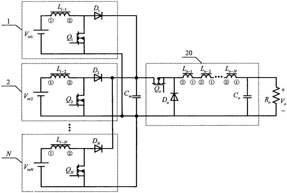
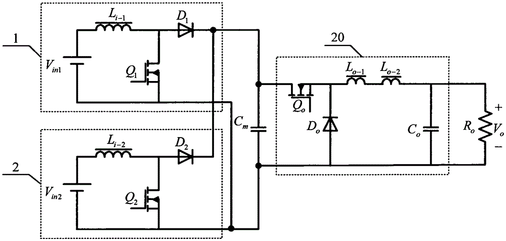
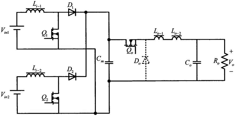
[0025] The present invention adopts the method of cascading the step-up circuit and the step-down circuit to realize the buck-boost conversion between the input source and the load voltage, so as to meet the needs of wide range variation of the input source voltage; adopts the method of parallel connection of the step-up circuit to realize power expansion , that is, the input of each step-up circuit can be the same type of input source, or a different type of input source, so as to meet the application requirements of the distributed power generation system, and at the same time reduce the current stress of the switch tube in the single step-up circuit; Independent control of each boost circuit reduces the difficulty of implementing each boost circuit and improves the overall efficiency of the converter; by coupling the filter inductance in the boost circuit and the step-dow...


PUM


Abstract

The invention discloses a parallel multi input coupled inductor buck and boost converter which belongs to the technical field of power electronic converting. The converter is composed of N boost circuits, a buck circuit (20) and a load, wherein N is a natural number more than one. Each boost circuit is composed of an input source, a filtering inductor, a switch tube, a diode and a filtering capacitor. The buck circuit is composed of a switch tube, a diode, a filtering inductor and a filtering capacitor. The output ends of N boost circuits are connected in parallel and then are connected with the input end of the buck circuit (20). The output end of the buck circuit (20) is connected with the load. The filtering inductors of N boost circuits are respectively coupled with the filtering inductor of the buck circuit. According to the converter provided by the invention, a number of input sources power the load at the same time; buck and boost converting between input and output is realized; the filtering inductors are coupled with each other; the converter has the advantage of small size; different input sources and the load side can be respectively and independently controlled; and the control is simple.

Description

technical field [0001] The invention relates to a parallel multi-input coupled inductance buck-boost converter, which belongs to the technical field of power electronic converters, and particularly relates to the technical field of power converters in the technical field of new energy power generation. Background technique [0002] With the increasingly serious energy crisis and environmental pollution, the development and utilization of solar energy, wind energy, fuel cells and other new and renewable energy sources have received more and more attention. Distributed power generation systems have become a focus of attention and research in countries all over the world. However, the inherent defects of new energy power generation equipment have brought some new problems and challenges, such as: the response speed of the fuel cell is relatively slow, and the output power cannot track the change of the load in time; Due to the influence of changes in natural conditions such as ...

Claims


Application Information

Patent Timeline
Patent Type & Authority Patents(China)
IPC IPC(8): H02M3/04H02M3/10
Inventor 张君君吴红飞邢岩王晶晶
Owner NANJING UNIV OF AERONAUTICS & ASTRONAUTICS
Why Eureka
Try Eureka