Distribution method and distributer of wireless WiFi multimedia broadcast system
A multimedia broadcasting and distributor technology, applied in the direction of selective content distribution, image communication, electrical components, etc., can solve problems such as powerlessness, achieve the effects of reducing congestion, improving controllability, and facilitating implementation
- Summary
- Abstract
- Description
- Claims
- Application Information
AI Technical Summary
Problems solved by technology
Method used
Image

Examples
Embodiment Construction
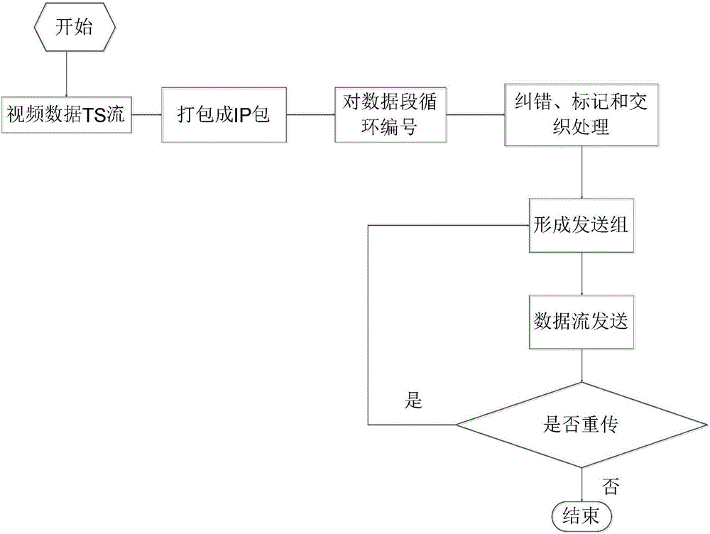
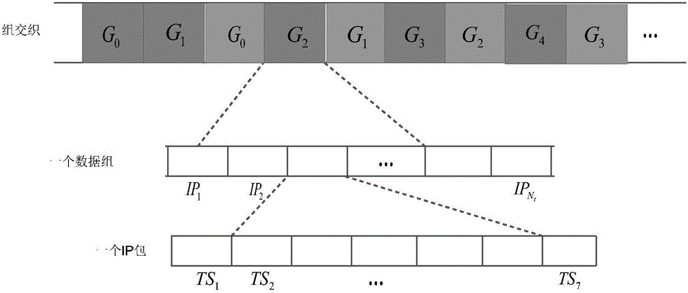
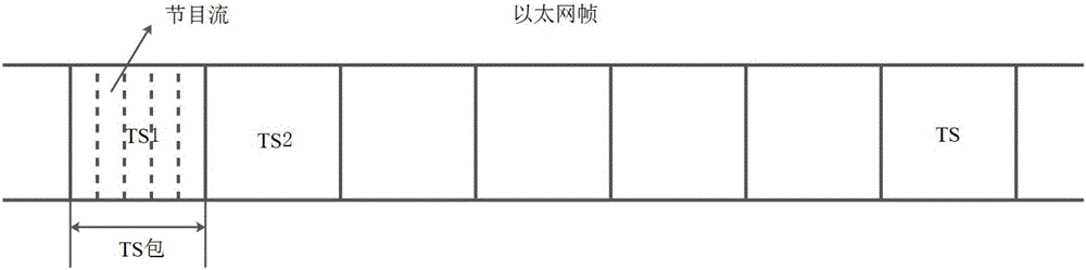
[0037] The technical scheme of the invention is as follows: firstly, multiple channels of video data streams are received and processed simultaneously to obtain multi-program multiplexing streams. Then, cycle number all data segments. Error correction and label processing are performed on each channel. Finally, according to the size of each video program stream, it is grouped and interleaved adaptively, and then sent in the form of multi-channel program data, that is, multiple program data streams are received and sent at the same time. In this way, the transmission and distribution of multi-channel video program data in the wireless WiFi system can be easily realized, and the simultaneous access of multi-programs and general multi-users can be realized.
[0038] Specifically, a distribution method of a wireless WiFi multimedia broadcasting system, such as figure 1 shown, including the following steps:
[0039] Step A, collecting multiplexed streams of video programs.
[0...
PUM
 Abstract
Description
Claims
Application Information
PatSnap Eureka turns technology decisions into work you can execute. Powered by our Innovation Knowledge Graph, it runs expert workflows across engineering, life sciences, materials and intellectual property. Get your review-ready output in minutes.


