Automatic anti-collision passage gate machine and control method thereof

A control method and technology of access gates, which are applied in the directions of roads, roads, traffic restrictions, etc., can solve the problems of positioning overshoot, jitter, noise, etc., and achieve the effect of smooth operation of the gate and low noise.

Active Publication Date: 2017-05-03
李杰成
View PDF5 Cites 4 Cited by
  • Summary
  • Abstract
  • Description
  • Claims
  • Application Information

AI Technical Summary

Problems solved by technology

[0021] The technical problem to be solved by the embodiment of the present invention is to provide a kind of application of the brushless DC motor with Hall in the channel gate, and make good use of the characteristics of the brushless motor to solve the problem of anti-collision and solve the problem of positioning The problem of overshoot solves the problem of jitter and noise during operation

Method used


Image

  • Automatic anti-collision passage gate machine and control method thereof
  • Automatic anti-collision passage gate machine and control method thereof
  • Automatic anti-collision passage gate machine and control method thereof

Examples


Embodiment 1

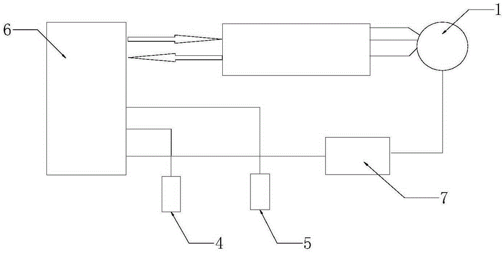
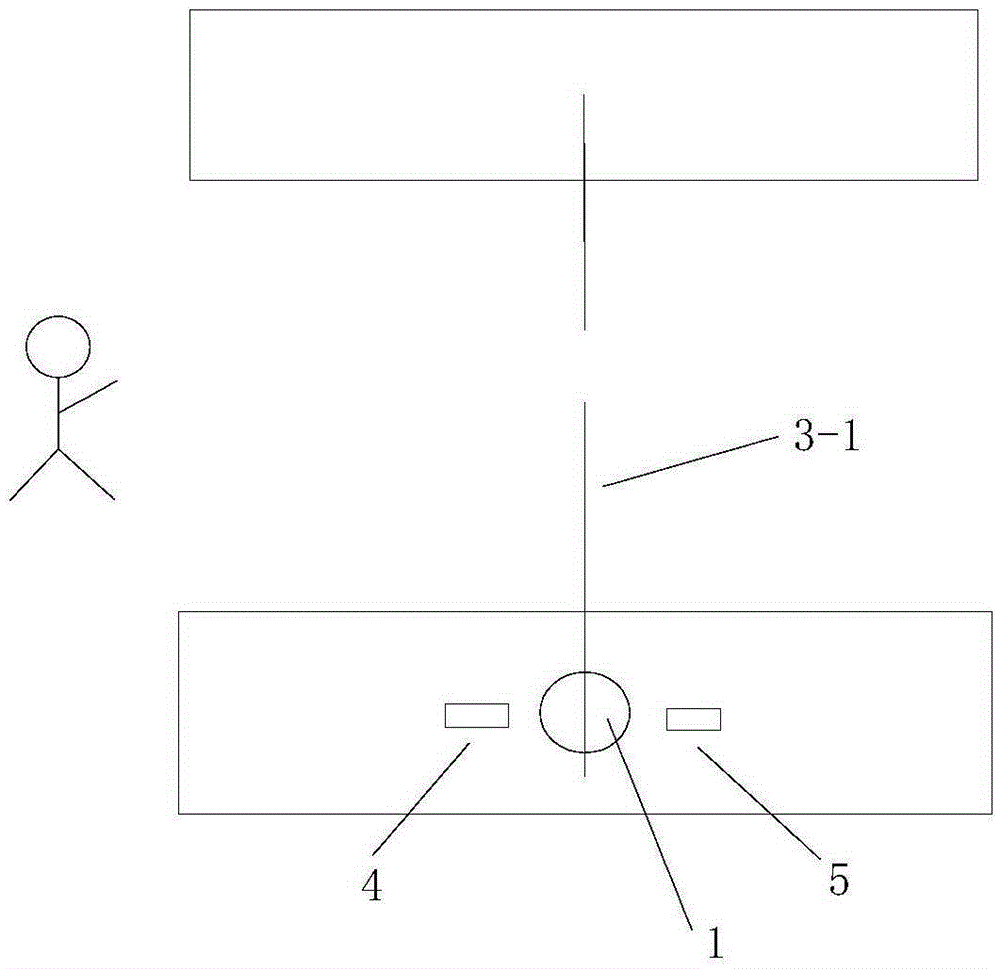
[0050] Such as figure 1 As shown, it includes a gate and a brushless DC motor 1 with a Hall sensor installed in the gate, and a brushless DC motor with a Hall sensor is also provided in the gate for driving and current control. The CPU6 of the Hall sensor brushless DC motor, a current detection device 7 is also arranged between the CPU6 and the Hall sensor brushless DC motor; A sensor 4 and B sensor 5 are also arranged in the gate, and the A, B The sensors are respectively connected to the CPU6; when the power is initially turned on, the brushless DC motor 1 is driven to rotate, and the signal returned by the Hall sensor of the motor is analyzed to convert the coordinate value, and the brushless DC motor 1 drives the swing arm 3-1 to rotate, When the swing arm 3-1 rotated to the A sensor 4, the CPU recorded this point as 0 coordinate value, and used this point as the position point for opening the door in this direction. Then the motor rotates in reverse, and after the swing ...

Embodiment 2

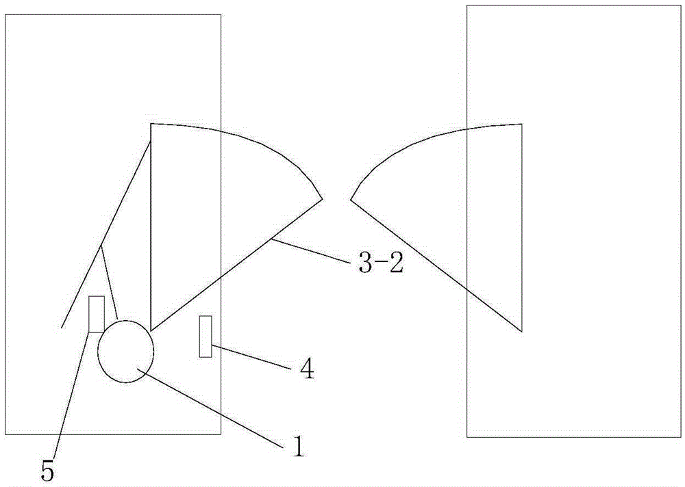
[0054] When the power is initially turned on, the brushless DC motor 1 is driven to rotate, and the signal returned by the motor Hall sensor is analyzed to convert the coordinate value. The brushless DC motor drives the rocker device, and the rocker device then pushes the wing 3-2 to move. When the wing 3-2 touches the B sensor 5, the CPU takes the signal of the B sensor 5, records the current position as the coordinate 0, and records it as the door opening coordinate, and then drives the motor to reverse, and when the wing touches the A sensor 4, it stops , the CPU records the current point as the door closing coordinates.

[0055] When the wing 3-2 catches a person or something by accident during closing the door, the CPU judges that there is an accident by detecting the change of the current, and at this moment reverses to open the door. Effectively prevent injury or damage to machinery.

[0056] In normal operation, according to the stroke (coordinate value), the motor ca...

Embodiment 3

[0059] When the power is initially turned on, the brushless DC motor 1 is driven to rotate, and the signal returned by the motor Hall sensor is analyzed to convert the coordinate value, and the brushless DC motor is brought to the turntable 3-3 to rotate. When the protrusion on the turntable 3-3 When the A sensor 4 has a signal, the CPU records this point as 0 coordinates. After several laps of operation, the system calculates the number of steps in each lap, and divides the number of steps into thirds (in the cross gate, it is quartered) to obtain Figure out the travel each rod (roller) will move during normal operation. Set the coordinates of the initial rod (roller) through the system (the system will save it, no need to set it next time), and it can work normally.

[0060] When there is an illegal push rod (collision), the CPU detects the change of the coordinate value, and according to the direction of the change, a reverse rotational torque is applied to the motor to pre...


PUM


Abstract

The embodiment of the invention discloses an automatic anti-collision passage gate machine. The automatic anti-collision passage gate machine comprises a gate machine body and a brushless direct current motor provided with a hall sensor and arranged in the gate machine body. The gate machine body is internally provided with a CPU which is connected with the brushless direct current motor with the hall sensor and used for driving and controlling the brushless direct current motor with the hall sensor through currents, and a current detecting device is arranged between the CPU and the brushless direct current motor with the hall sensor. The gate machine body is further provided with a sensor A and a sensor B inside. The sensor A and the second B are connected with the CPU. The application of the brushless direct current motor with the hall sensor to the passage gate machine is provided, the characteristics of the brushless motor are utilized, the anti-collision problem is solved, the positioning overshooting problem is solved, and the shaking and noise problems in service are solved. The automatic anti-collision passage gate machine is simple in mechanical structure and convenient to install and debug.

Description

technical field [0001] The invention relates to the field of gates, in particular to an automatic anti-collision channel gate and a control method thereof. Background technique [0002] There are currently three main types of pedestrian passage gates: swing gates, wing gates, tripod gates (or cross gates) [0003] 1. Swing gate: [0004] The first type: the swing arm of the swing gate is positioned by three sensors at the two door opening points and the middle door closing point. The swing arm is driven by a motor to open the door according to the need for pedestrians to pass through. After the passerby, the swing arm returns to the door closing position, and the swing arm is locked through the mechanical structure. [0005] The second type: the positioning of the swing gate is positioned by an absolute value rotary encoder, and the opening point and the closing point are the coordinate points generated by the rotary encoder. In the door closing position, when an illegal ...

Claims


Application Information

Patent Timeline
Patent Type & Authority Applications(China)
IPC IPC(8): E01F13/04H02P6/17
CPCE01F13/04
Inventor 李杰成
Owner 李杰成
Why Eureka
Try Eureka