Color wheel assembly and projection device

A color wheel and component technology, applied in projection devices, optics, instruments, etc., can solve the problems of high working noise and low heat dissipation efficiency of color wheels, achieve good noise reduction, shorten heat conduction path, and increase heat exchange area Effect

Active Publication Date: 2017-05-03
APPOTRONICS CORP LTD
View PDF10 Cites 5 Cited by
  • Summary
  • Abstract
  • Description
  • Claims
  • Application Information

AI Technical Summary

Problems solved by technology

[0004] The invention provides a color wheel assembly and a projection device to solve the problems of low heat dissipation efficiency and high working noise of the existing color wheel

Method used


Image

  • Color wheel assembly and projection device
  • Color wheel assembly and projection device
  • Color wheel assembly and projection device

Examples


Embodiment 1

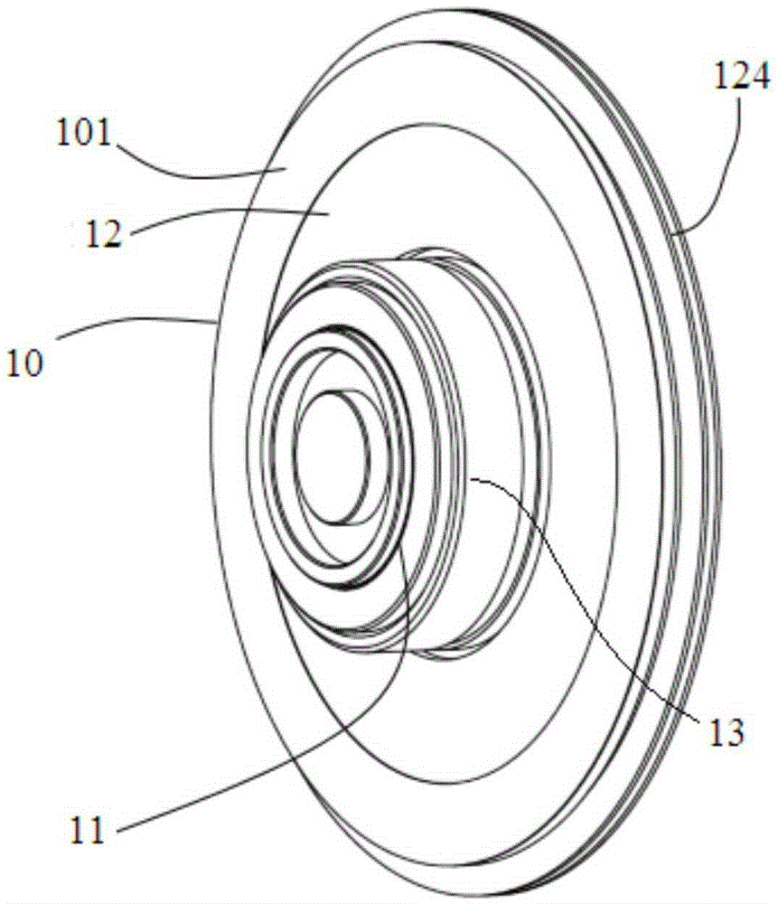
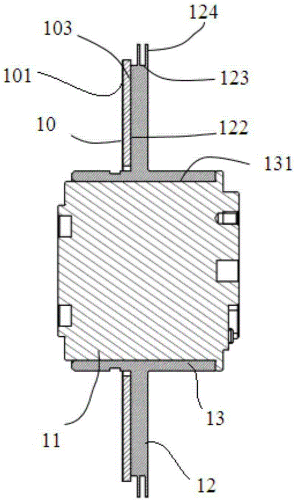
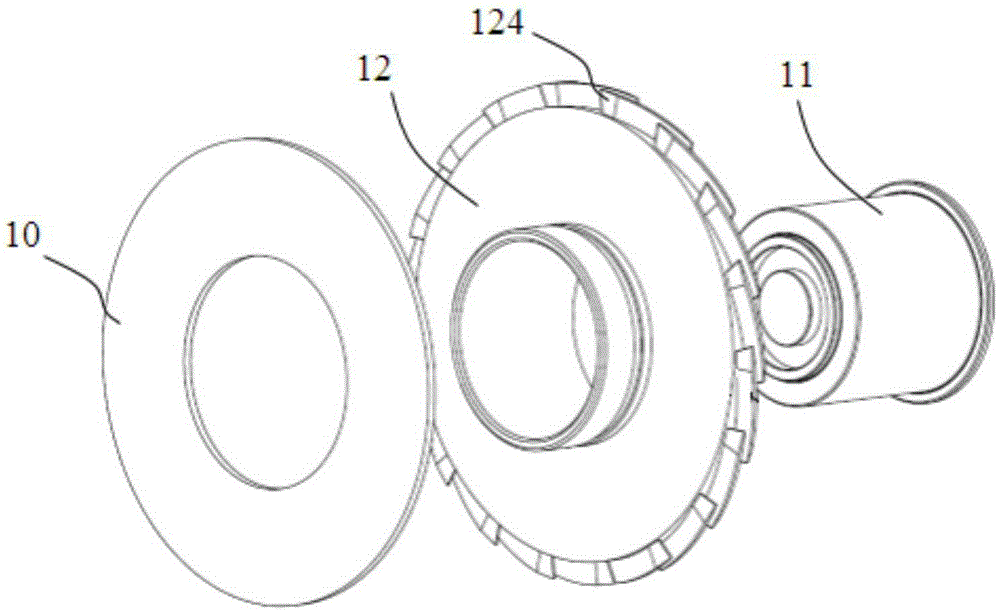
[0024] The color wheel assembly provided in this embodiment, such as figure 1 As shown, it includes a color wheel 10, a color wheel substrate 12, and a driving device for driving the color wheel substrate 12 to rotate. The color wheel 10 and the color wheel substrate 12 are both disc-shaped, and the driving device is a motor 11. A heat sink 124 is provided on the outer edge of the color wheel substrate 12, and the heat sink 124 protrudes from the side surface 123 of the color wheel substrate 12. The diameter of the outer circle of the color wheel substrate 12 matches (that is, the same or similar) to the outer diameter of the fluorescent area 101 of the color wheel, and the fluorescent area 101 of the color wheel 10 is arranged on the outer edge of the color wheel 10 in an annular band. The fluorescent area 101 is the heating area of ​​the color wheel 10. The heat sink 124 is arranged on the outer edge of the color wheel substrate 12, so that the heat transfer path from the pho...

Embodiment 2

[0033] The color wheel assembly given in this embodiment is improved on the basis of the first embodiment, such as image 3 As shown, in this embodiment, the heat sink 124 is arranged at an oblique angle on the side surface 123 of the color wheel substrate 12, and the two ends of the heat sink 124 are respectively flush with the two axial end surfaces of the color wheel substrate 12. The surface of 124 and the axial direction of the color wheel substrate 12 form a specific included angle, that is, the heat sink 124 is inclined at a certain angle with respect to the axial end surface of the color wheel substrate 12. In other words, each individual heat sink 124 starts from the outer edge of one end surface of the color wheel substrate 12 in the axial direction, and extends along the side surface 123 of the color wheel substrate 12 to the other end surface of the color wheel substrate 12 in the axial direction. It is similar to the multi-vortex fan structure provided on the side s...

Embodiment 3

[0036] The color wheel assembly given in this embodiment is an improvement of the previous embodiment, such as Figure 4 As shown, the heat sink 124 in this embodiment has an airfoil structure, that is, the cross section of the heat sink 124 along the circumferential direction of the color wheel substrate 12 is roughly in the shape of a droplet with one thick end and thin end, and the overall heat sink 124 resembles an airplane wing. . The relatively thick end of the heat sink 124 faces an axial end surface of the color wheel substrate 12 and is located at the windward end of the axial airflow generated by the heat sink 124 when the color wheel substrate 12 rotates; The end of the heat sink 124 with a relatively thin thickness is tapered to extend toward the two axial ends of the color wheel substrate 12 and is located at the wake end of the axial air flow, that is, the end with a larger thickness of the airfoil structure is provided At the windward end of the heat sink 124, an...


PUM


Abstract

The invention provides a color wheel assembly and a projection device. The color wheel assembly comprises a color wheel, a color wheel substrate used for fixing the color wheel, and a drive device which is used for driving the rotation of the color wheel substrate. Heat sinks are arranged on the outer edge of the color wheel substrate. The heat sinks project on the side surface of the color wheel substrate. The color wheel substrate and the color wheel are circular. An annular fluorescent zone is arranged on the surface of the color wheel. The diameter of the color wheel substrate matches the outer edge diameter of the fluorescent zone of the color wheel. According to the invention, a number of heat sinks are arranged on the side surface of the color wheel substrate, which shortens the heat conduction path between the heat generating zone of the color wheel and the heat sinks and increases the heat exchange area between the color wheel and air; the heat sinks and the axial direction of the color wheel form a certain angle; the color wheel assembly can acquire stable axial air convection; and the heat sinks are arranged in an airfoil structure as a whole, which further increases the heat dissipation face and air convection, and plays a good role of noise reduction.

Description

Technical field [0001] This application relates to a light source device, in particular to a color wheel assembly and a projection device. Background technique [0002] Some existing projection devices use laser light generated by a laser light source to excite a fluorescent color wheel technology to generate color light sequences. However, as the output light power of this type of product increases, the thermal power consumption on the color wheel also increases. If the heat dissipation problem of the color wheel cannot be solved well, it will greatly reduce the efficiency of the phosphor by the excitation light, and even cause Damage to the color wheel itself. The color wheel is mainly rotated at a high speed to exchange heat with the air to achieve cooling. Therefore, to improve the heat dissipation effect of the color wheel, it is necessary to enhance the convective heat exchange efficiency of the color wheel. [0003] In the prior art, in order to further improve the convect...

Claims


Application Information

Patent Timeline
Patent Type & Authority Applications(China)
IPC IPC(8): G03B21/20G03B21/16
CPCG03B21/16G03B21/20
Inventor 谭大治
Owner APPOTRONICS CORP LTD
Why Eureka
Try Eureka