A color wheel assembly and projection device
A color wheel and component technology, applied in projection devices, instruments, optics, etc., can solve the problems of high working noise and low heat dissipation efficiency of the color wheel, achieve good noise reduction effect, shorten heat conduction path, increase heat dissipation surface and air convection effect
- Summary
- Abstract
- Description
- Claims
- Application Information
AI Technical Summary
Problems solved by technology
Method used
Image
Examples
Embodiment 1
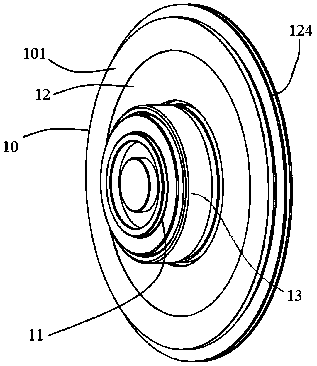
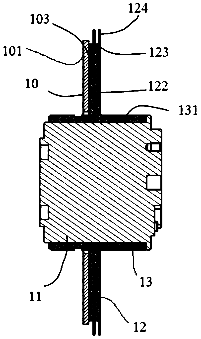
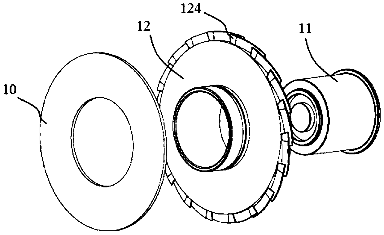
[0024] The color wheel assembly provided by this embodiment, such as figure 1 As shown, it includes: a color wheel 10 , a color wheel base plate 12 , and a driving device for driving the color wheel base plate 12 to rotate, wherein both the color wheel 10 and the color wheel base plate 12 are disc-shaped, and the driving device is a motor 11 . The outer edge of the color wheel substrate 12 is provided with a cooling fin 124 protruding from the side surface 123 of the color wheel substrate 12 . Wherein, the diameter of the outer circle of the color wheel substrate 12 matches (i.e. is equal to or similar to) the diameter of the outer edge of the fluorescent area 101 of the color wheel, and the fluorescent area 101 of the color wheel 10 is arranged on the outer edge of the color wheel 10 in a ring-shaped distribution. The fluorescent area 101 is the heat generating area of the color wheel 10 . The heat sink 124 is arranged on the outer edge of the color wheel substrate 12, so ...
Embodiment 2
[0033] The color wheel assembly provided in this embodiment is improved on the basis of Embodiment 1, as image 3 As shown, in this embodiment, the heat sink 124 is arranged on the side surface 123 of the color wheel base plate 12 at an inclined angle, and the two ends of the heat sink 124 are flush with the two axially corresponding end faces of the color wheel base plate 12 respectively. The surface of the heat sink 124 forms a specific included angle with the axial direction of the color wheel base plate 12 , that is, the cooling fin 124 is inclined at a certain angle relative to the axial end surface of the color wheel base plate 12 . In other words, each cooling fin 124 starts from the outer edge of one axial end surface of the color wheel base plate 12 and extends along the side surface 123 of the color wheel base plate 12 to the other axial end surface of the color wheel base plate 12, so that the plurality of cooling fins 124 as a whole Similar to the multi-scroll fan ...
Embodiment 3
[0036] The color wheel assembly provided in this embodiment is an improvement to the previous embodiment, as Figure 4 As shown, the heat sink 124 in this embodiment has an airfoil structure, that is, the cross section of the heat sink 124 along the circumferential direction of the color wheel substrate 12 is roughly in the shape of a water droplet with one end thick and the other end thin, and the heat sink 124 as a whole is similar to the wing of an aircraft . The relatively thicker end of the heat sink 124 faces an axial end surface of the color wheel base plate 12 and is located at the windward end of the axial airflow generated by the heat sink 124 when the color wheel base plate 12 rotates; The relatively thinner end of the heat sink 124 is tapered toward the two axial ends of the color wheel base plate 12 and is located at the wake end of the axial airflow, that is, the thicker end of the airfoil structure is set At the windward end of the heat sink 124 , the relativel...
PUM
 Abstract
Description
Claims
Application Information
 - R&D
- Intellectual Property
- Life Sciences
- Materials
- Tech Scout
- Unparalleled Data Quality
- Higher Quality Content
- 60% Fewer Hallucinations
Browse by: Latest US Patents, China's latest patents, Technical Efficacy Thesaurus, Application Domain, Technology Topic, Popular Technical Reports.
© 2025 PatSnap. All rights reserved.Legal|Privacy policy|Modern Slavery Act Transparency Statement|Sitemap|About US| Contact US: help@patsnap.com


