Part die of stirring disc

A stirring plate and mold technology, applied in the direction of manufacturing tools, casting molding equipment, metal processing equipment, etc., can solve the problems that cannot be mass-produced and difficult to meet market demand

Pending Publication Date: 2017-05-10
GUANGDONG POLYTECHNIC NORMAL UNIV
View PDF6 Cites 0 Cited by
  • Summary
  • Abstract
  • Description
  • Claims
  • Application Information

AI Technical Summary

Problems solved by technology

[0005] In order to overcome the disadvantages that there is no mold dedicated to processing stirring plate parts, the present invention cannot be produced quickly and in batches, and it is difficult to meet the market demand. The technical problem to be solved by the present invention is to provide a stirring plate Parts mold

Method used


Image

  • Part die of stirring disc
  • Part die of stirring disc
  • Part die of stirring disc

Examples


Embodiment 1

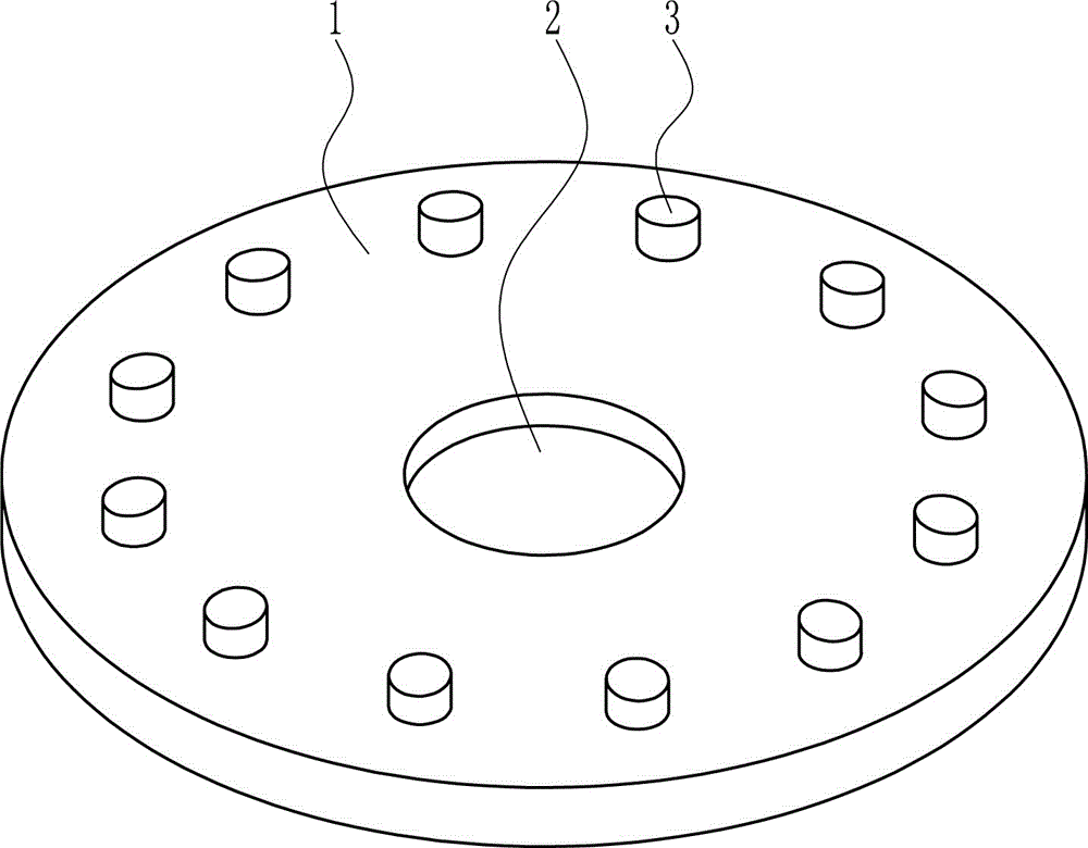
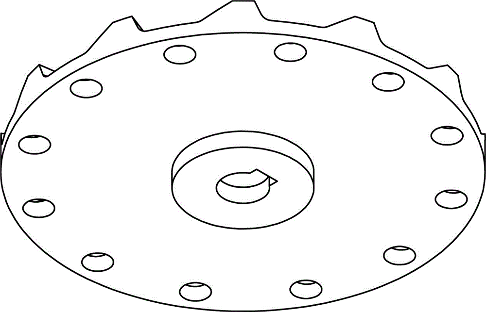
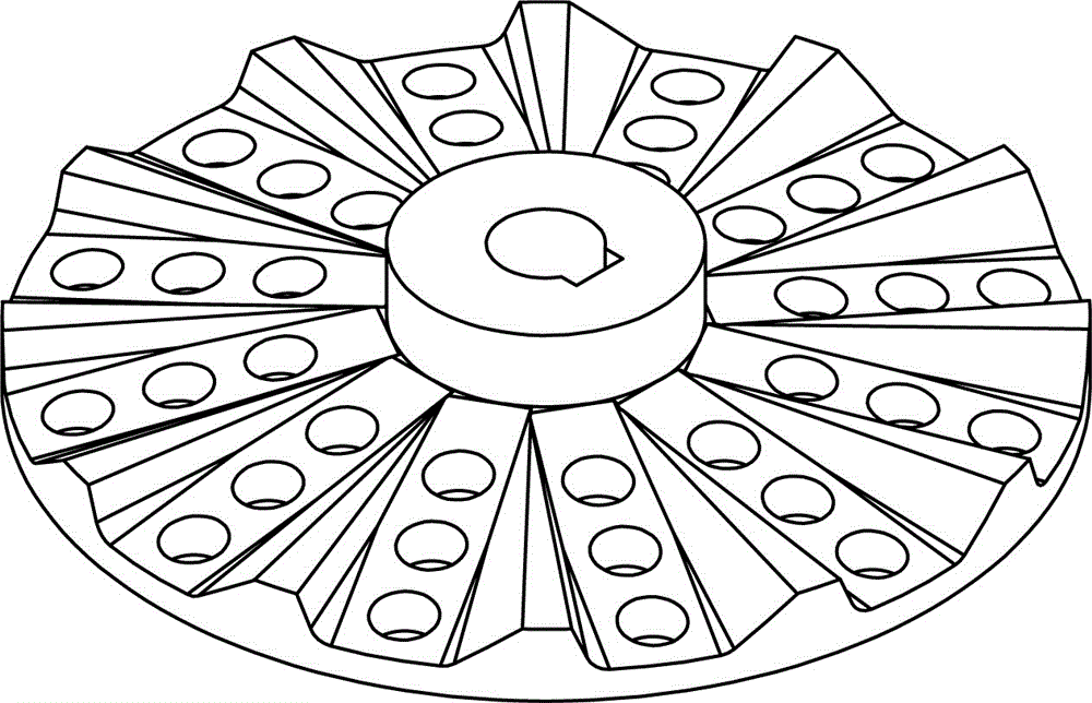
[0027] A stirring plate parts mold, such as Figure 1-6 As shown, it includes an upper mold body 1, a first round bump 3, a lower mold body 4, a second round bump 7, a key-shaped bump 8, an elongated bump 9 and a third round bump 10, and the upper mold The middle part of the body 1 is provided with a first circular groove 2, and the upper mold body 1 has a plurality of first circular protrusions 3 in an annular array; the lower mold body 4 is provided with a large circular groove 5, and the middle part of the large circular groove 5 is set There is a second round groove 6, and a second round bump 7 and a key-shaped bump 8 are arranged in the second round groove 6, and the second round bump 7 is tangent to the key-shaped bump 8, and inside the large round groove 5 There are a plurality of elongated bumps 9 in the annular array, and two third circular bumps 10 are arranged on each elongated bump 9 , and the lower mold body 4 is used in combination with the upper mold body 1 .

...


PUM

PropertyMeasurementUnit
Diameteraaaaaaaaaa
Heightaaaaaaaaaa

Abstract

The invention relates to a die, in particular to a part die of a stirring disc, which aims at solving the technical problem of providing a part die of a stirring disc. To solve the technical problem, the part die of the stirring disc comprises an upper die body, first circular convex blocks, a lower die body, second circular convex blocks, key-shaped convex blocks and the like, wherein the middle part of the upper die body is provided with a first circular groove, and the first circular convex blocks are arranged on the upper die body in an annular array way; the lower die body is provided with a large circular groove, the middle part of the interior of the large circular groove is provided with a second circular groove, the second circular convex blocks and the key-shaped convex blocks are arranged in the second circular groove, and the second circular convex blocks are tangential with the key-shaped convex blocks. The part die of the stirring disc has the advantage that by adopting the structure type of multiple grooves and convex blocks, casting equipment is used for casting and forming the material at one time, so as to realize the quick continuous and batched production.

Description

technical field [0001] The invention relates to a mould, in particular to a part mould for a stirring plate. Background technique [0002] The mold has a specific contour or cavity shape, and the application of the contour shape with a cutting edge can separate the blank according to the contour line shape (punching). Applying the shape of the inner cavity can make the blank obtain the corresponding three-dimensional shape. The mold generally includes two parts, the movable mold and the fixed mold, which can be separated or combined. Take out the parts when they are separated, and inject the blank into the mold cavity to form when they are closed. The mold is a precision tool with a complex shape and bears the bulging force of the billet. It has high requirements for structural strength, stiffness, surface hardness, surface roughness and machining accuracy. The development level of mold production is one of the important symbols of the level of mechanical manufacturing. ...

Claims


Application Information

Patent Timeline
IPC IPC(8): B22C9/22
CPCB22C9/22
Inventor 姚屏
Owner GUANGDONG POLYTECHNIC NORMAL UNIV
Why Eureka
Try Eureka