
A single-tube air cannon capable of continuous firing

A technology for launching tubes and air cannons, which is used in compressed air guns, weapons without explosives, and testing of machine/structural components, etc. It can solve the problems of complex structure, difficult to achieve precise control of impact interval, and large distribution range.

Active Publication Date: 2021-07-16
CHINA AIRPLANT STRENGTH RES INST
View PDF5 Cites 0 Cited by
  • Summary
  • Abstract
  • Description
  • Claims
  • Application Information

AI Technical Summary

Problems solved by technology

[0005] In addition to the composite material structure, the radome, windshield glass, engine nacelle, and engine fan blades of the aircraft also need to undergo hail impact tests. For example, the windshield glass and radome require continuous hail impact tests in the area to evaluate the radome. Changes in the bearing characteristics and electromagnetic characteristics of the structure, and at the same time evaluate the impact of bird strike resistance and optical properties on the transparent parts of the windshield after hail impact, but there is no similar test device for single-point continuous impact tests in China
[0006] In engineering practice, there is a test system that achieves continuous impact through sequential firing of multiple barrels, such as the 9-tube or even 16-tube air cannon used in the bird swallowing test of the engine test bench. Mechanism, multiple sets of single-tube launching mechanisms are combined through the test bench to achieve the purpose of continuous launching. This kind of experimental system has an extremely complex structure and high cost, and it cannot guarantee the accuracy of the impact position of the projectile, and the dispersion range is large. It is difficult to achieve precise control of the impact interval, and it is mostly used to simulate continuous impact in the area

Method used


Image

  • A single-tube air cannon capable of continuous firing

Examples


Embodiment Construction

[0022] The following describes the implementation of the technical solution of the present invention in detail in conjunction with the accompanying drawings.

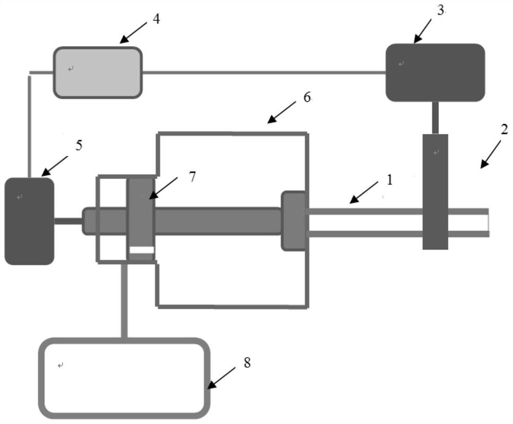
[0023] Such as figure 1 As shown, the device of the present invention is composed of a launching air chamber, a gun barrel, an air supply chamber, an air source, a combined valve body, a loading device, an electric servo actuator for launching / supplementing air, an electric servo actuator for loading bullets, and a control valve. The system consists of compressed air as the working medium. The loading device and tooling are equipped with multiple projectiles, which are connected with the barrel through a high-precision chute. One projectile is fired at a time, and the next projectile is pushed into the waiting area according to the control command under the action of the servo actuator for loading. launch location.

[0024] The launch chamber and the gun barrel are sealed by the cone of the combined valve body, which ...


PUM


Abstract

The invention discloses a single-tube air cannon capable of continuous firing, which comprises a launching tube 1, a loading device 2, an electric servo actuator 3 for loading, an experimental control system 4, and an electric servo actuator for launching / air supply 5. Launching air chamber 6, combined valve body 7; air supply chamber 8; wherein, the launching tube 1 is connected to the loading device 2, and a plurality of projectiles can be preset in the loading device 2, and an electric servo is used for loading. Under the push of the actuator 3, a projectile enters the launching tube at a time; the launching tube 1 is connected with the launching air chamber 6, and the launching air chamber is a stepped cylindrical structure of a spiral body, which is composed of a large chamber at the right end and a small chamber at the left end; The small chambers of chamber 6 and air supply chamber 8 are connected by an air path; the technical scheme of the present invention can meet the test requirements of continuous foreign object impact on high-speed moving machines such as aircraft structures, high-speed train structures, and wind turbine blades, and can also be set by adjusting control parameters. Specifies the interval or frequency of transmissions.

Description

technical field [0001] The invention belongs to the field of research and development of a special impact test loading device, which is used for realizing continuous impact loading of projectiles, and can adjust the firing interval and firing quantity according to loading requirements. Background technique [0002] Composite materials have the advantages of high specific strength, high specific stiffness, strong designability, and good fatigue resistance. They can significantly reduce structural weight, improve structural load-bearing efficiency, and reduce operating costs. Modern aircraft, high-speed rail, etc. are increasingly using composite materials. . The proportion of composite materials on Boeing 787 and A350XWB can reach more than 50%. The amount of composite materials has become an important reference to measure the advanced level of modern civil aircraft. In order to reduce energy consumption, the field of high-speed rail is also carrying out research and applica...

Claims


Application Information

Patent Timeline
Patent Type & Authority Patents(China)
IPC IPC(8): F41B11/50F41B11/60F41B11/72G01M7/08
Inventor 刘小川
Owner CHINA AIRPLANT STRENGTH RES INST
Learn More