
Three-freedom-degree parallel spindle head mechanism suitable for horizontal machining

A degree of freedom, spindle head technology, used in metal processing mechanical parts, metal processing equipment, manufacturing tools, etc., can solve the problems of high stiffness, low motion inertia, and poor dynamic isotropy, and achieve high stiffness and load capacity. Strong, low mass effect

Inactive Publication Date: 2017-05-10
CHANGCHUN UNIV OF SCI & TECH
View PDF9 Cites 2 Cited by
  • Summary
  • Abstract
  • Description
  • Claims
  • Application Information

AI Technical Summary

Problems solved by technology

[0005] The purpose of the present invention is to overcome the shortcomings of the traditional tandem spindle head structure and the problem of poor isotropic dynamic performance of the existing parallel spindle head with a symmetrical structure, and provide a horizontal three-degree-of-freedom parallel spindle head mechanism to make it The spindle head mechanism has the characteristics of high rigidity, low motion inertia, and good dynamic performance isotropy, which weakens the influence of branch chain gravity on the dynamic characteristics of the horizontal spindle head structure, and can achieve high speed and high precision when applied to five-axis hybrid machine tools processing

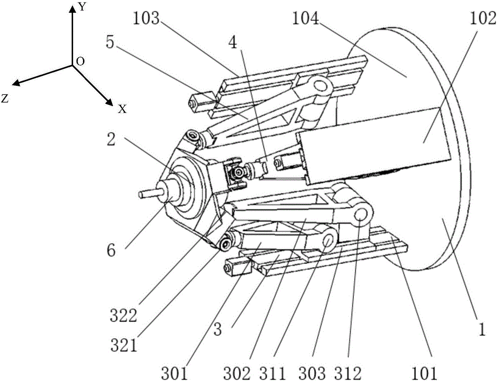
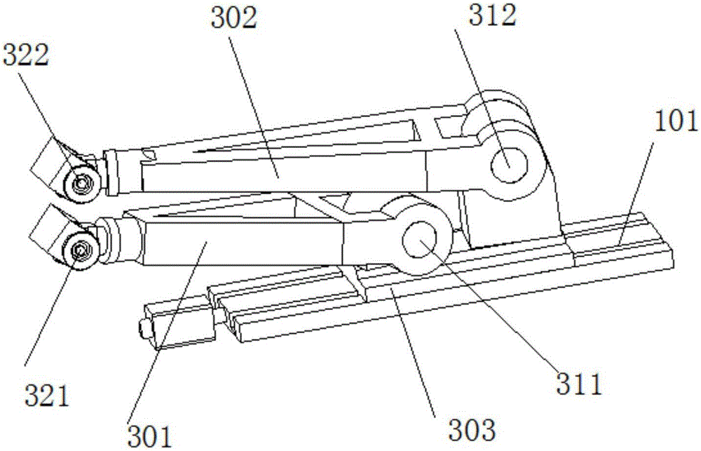
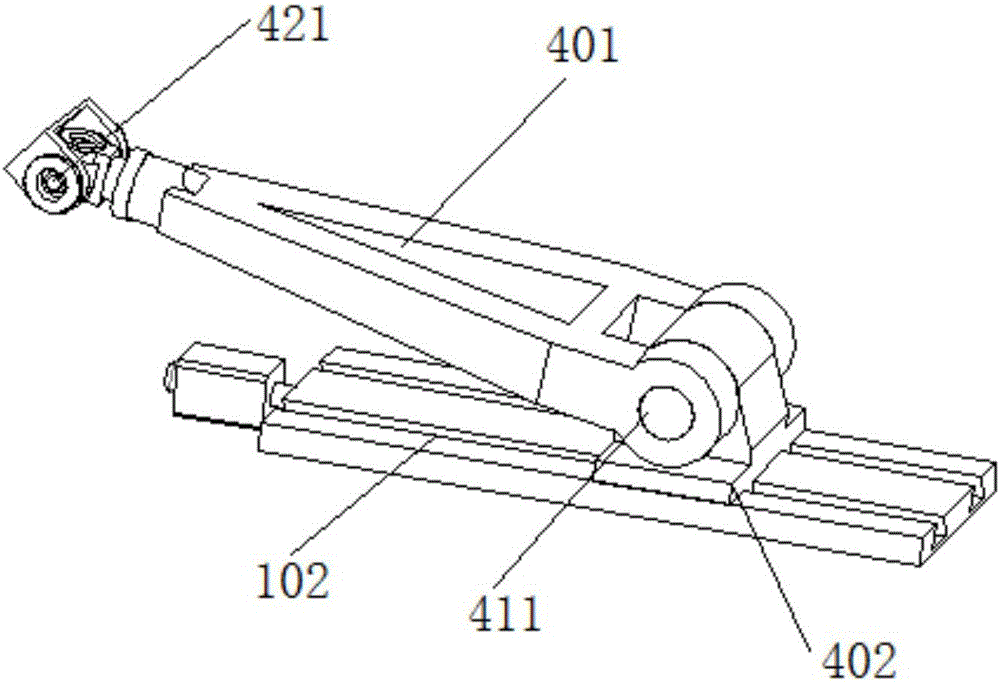
Method used


Image

  • Three-freedom-degree parallel spindle head mechanism suitable for horizontal machining
  • Three-freedom-degree parallel spindle head mechanism suitable for horizontal machining
  • Three-freedom-degree parallel spindle head mechanism suitable for horizontal machining

Examples


Embodiment Construction

[0013] The structure, principle and specific implementation of the present invention will be further described below in conjunction with the accompanying drawings.

[0014] figure 1 The three-dimensional structural schematic diagram of the embodiment of the horizontal three-degree-of-freedom parallel spindle head mechanism provided by the present invention, the horizontal three-degree-of-freedom parallel spindle head mechanism structure includes a fixed platform 1, a moving platform 2, and a spindle 6, and is arranged on the The first branch 3 , the second branch 4 and the third branch 5 of the fixed platform 1 and the moving platform 2 constitute a parallel spindle head mechanism with three degrees of freedom in space. The fixed platform 1 includes a first frame 101, a second frame 102, a third frame 103 and a base 104, the first frame 101, the second frame 102 and the third frame 103 are fixed on the base 104 and The space is evenly distributed, and the first branch 3, the ...


PUM


Abstract

The invention provides a three-freedom-degree parallel spindle head mechanism suitable for horizontal machining and belongs to the field of machine manufacturing. The three-freedom-degree parallel spindle head mechanism comprises a movable platform, a fixed platform, a first branch, a second branch and a third branch, wherein a spindle is installed on the movable platform, and the first branch, the second branch and the third branch are connected between the movable platform and the fixed platform and are uniformly distributed in space. The first branch is installed at the bottom and comprises a sliding block and guide rail mechanism, a first connecting rod and a second connecting rod, and the two ends of each connecting rod are connected with a sliding block and the movable platform through a hooke joint and a ball pair correspondingly. The second branch comprises a sliding block and guide rail mechanism and a third connecting rod, and the two ends of the third connecting rod are connected with a sliding block and the movable platform through a revolving pair and a ball pair correspondingly. The third branch and the second branch are the same in structure. The horizontal three-freedom-degree parallel spindle head mechanism has the characteristics of being high in stiffness and load capacity, small in moving component mass, isotropic in dynamic performance and the like; and the first branch is provided with the dual connecting rods, thus, the influence of gravity on the horizontal mechanism can be weakened, and high-speed high-precision machining of a machine tool is achieved.

Description

technical field [0001] The invention belongs to the field of mechanical manufacturing, in particular to a three-degree-of-freedom parallel spindle head mechanism suitable for horizontal processing. Background technique [0002] The five-axis linkage CNC machine tool is an important processing equipment in the manufacturing industry. The traditional five-axis linkage CNC machine tool usually adopts a gantry structure. Or universal swing head to realize two rotary motions of AC axis or AB axis. The spindle deflection angle of this kind of five-axis CNC machine tool is relatively large, and it can achieve high rotation speed and acceleration on a single axis, but there is an automatic rotation of the swing angle during machining with a large swing angle, which causes milling damage to the parts; and the five-coordinate linkage processing equipment Due to the structural characteristics of the rotating coordinates, there is a phenomenon that the invalid path is long during high-...

Claims


Application Information

Patent Timeline
IPC IPC(8): B23B19/02
CPCB23Q1/70
Inventor 王煜天许金凯
Owner CHANGCHUN UNIV OF SCI & TECH
Learn More