Drilling equipment for drilling center hole of motor shaft

A technology of drilling equipment and motor shaft, which is applied in drilling/drilling equipment, boring/drilling, metal processing equipment, etc. The effect of simplicity, improved accuracy, and improved work efficiency

Inactive Publication Date: 2017-05-10
CHONGQING QIANYAN MACHINERY CO LTD
View PDF6 Cites 5 Cited by
  • Summary
  • Abstract
  • Description
  • Claims
  • Application Information

AI Technical Summary

Problems solved by technology

[0004] The purpose of the present invention is to provide a drilling device for drilling the center hole of the motor shaft, so as to solve the problem that the motor shaft is eccentric during the drilling process, resulting in low drilling accuracy and the problems that the holes at both ends of the motor shaft are not on the same axis.

Method used


Image

  • Drilling equipment for drilling center hole of motor shaft

Examples


Embodiment Construction

[0021] The present invention will be further described in detail below through specific implementations:

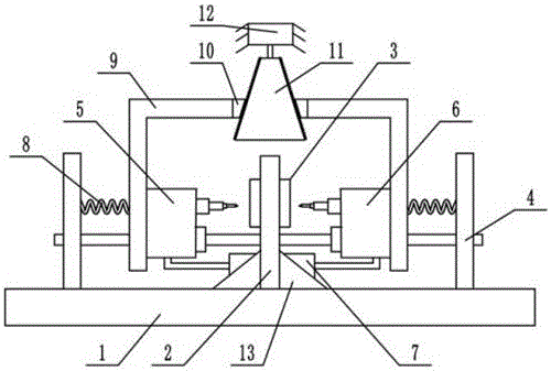
[0022] The reference signs in the drawings of the specification include: base 1, support plate 2, clamping device 3, sliding frame 4, first drilling machine 5, second drilling machine 6, first motor 7, elastic member 8, connecting The rod 9, the threaded plate 10, the threaded cone 11, the second motor 12, and the reinforcement device 13.

[0023] The embodiment is basically as attached figure 1 Shown:

[0024] The drilling equipment used to drill the center hole of the motor shaft is mainly composed of the base 1, the supporting plate 2, the clamping device 3, the sliding frame 4, the first drilling machine 5, the second drilling machine 6, the thread plate 10, and the thread cone. Body 11 constitutes. A support plate 2 is welded to the middle of the base 1, and a reinforcement device 13 is installed at the lower part of the support plate 2, and the reinforcement device 13 i...


PUM


Abstract

The invention belongs to the field of mechanical grinding, and concretely discloses drilling equipment for drilling a center hole of a motor shaft. The drilling equipment for drilling the center hole of the motor shaft comprises a base and a support plate. A through hole is formed in the support plate; a clamping device is arranged in the through hole and is coaxial to the through hole; a sliding support penetrates through the bottom part of the support plate; a first drilling machine is slidably connected to one end of the sliding support; a second drilling machine is slidably connected to the other end of the sliding support; the first drilling machine and the second drilling machine are jointly connected with a first motor; elastic elements are connected between the first drilling machine and one side wall of the sliding support as well as between the second drilling machine and the other side wall of the sliding support; drill bits of the first drilling machine and the second drilling machine are coaxial to the clamping device; connecting rods are connected onto the first drilling machine and the second drilling machine; threaded plates are arranged on opposite end faces of the two connecting rods; and a threaded cone is matched between the threaded plates. The scheme can prevent the occurrence of the problems that the motor shaft is eccentric during a drilling process, holes in two ends of the motor shaft are non-coaxial, and the like.

Description

Technical field [0001] The invention belongs to the field of mechanical grinding, and particularly relates to a drilling tool for a workpiece. Background technique [0002] The motor shaft is generally a long and slender article. When the motor shaft is processed, especially when the outer circumference of the motor shaft is processed as a whole, it is generally processed by a lathe. During processing, the motor shaft is positioned in the form of a rotating center, and the center needs to be positioned with the help of a center hole, so that both ends of the motor shaft need to be drilled. The drilling is generally performed by a drilling machine, that is, the workpiece is fixed on the fixture. The clamp is movable and movable. First, use a scribing needle to scribe on one end of the motor shaft to determine the center point, and then align the drill bit of the drilling machine to the center point for drilling. After drilling the holes on one end surface, you need to turn the mo...

Claims


Application Information

Patent Timeline
IPC IPC(8): B23B39/22
CPCB23B39/22
Inventor 罗贵良
Owner CHONGQING QIANYAN MACHINERY CO LTD
Why Eureka
Try Eureka