
Swing type clamping device

A clamping device and swing-type technology, applied in the field of mechanical processing, can solve problems such as workpiece damage, and achieve the effects of reasonable structure, good applicability, and good reliability

Inactive Publication Date: 2017-05-10
魏俊杰
View PDF10 Cites 11 Cited by
  • Summary
  • Abstract
  • Description
  • Claims
  • Application Information

AI Technical Summary

Problems solved by technology

Common clamping devices generally use the cylinder to directly drive the clamp block to clamp and loosen the workpiece, but often cause damage to the workpiece due to excessive clamping force

Method used


Image

  • Swing type clamping device
  • Swing type clamping device

Examples


Embodiment Construction

[0012] The present invention will be further described in detail below in conjunction with the accompanying drawings and examples. The following examples are explanations of the present invention and the present invention is not limited to the following examples.

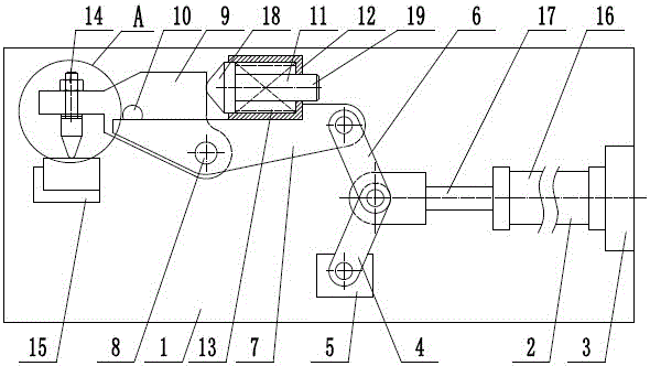
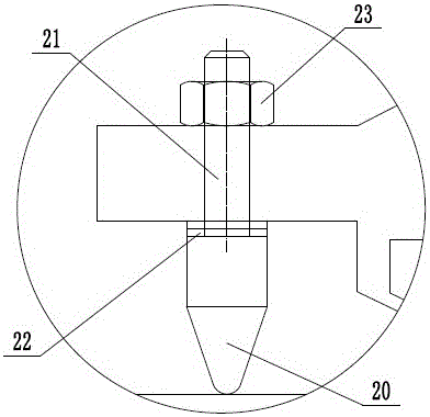
[0013] Such as figure 1 and figure 2 As shown, a swing clamping device includes a frame 1, a driving cylinder 2, a cylinder support 3, a rocker 4, a rocker support seat 5, a connecting rod 6, a lever 7, a support pin 8, and a pressure plate 9 , stop pin 10, sliding column 11, sliding column support 12, stage clip 13, clamping assembly 14, workpiece supporting seat 15, the lower end of described rocking bar 4 is hinged on the rocking bar supporting seat 5, the lever 7 The middle end is hinged on the frame 1 through a support pin 8, the right end of the lever 7 is hinged to the upper end of the connecting rod 6, the driving cylinder 3 includes a cylinder body 16 and a piston rod 17, and the cylinder body 16 is horiz...


PUM


Abstract

The invention provides a swing type clamping device and belongs to the technical field of machining. The swing type clamping device comprises a rocking rod, a connecting rod, a lever, a pressing plate, a pressure spring and a clamping assembly. The lower end of the rocking rod is hinged to a rocking rod supporting base. The middle end of the lever is hinged to a rack through a supporting hinge pin. The right end of the lever is hinged to the upper end of the connecting rod. The left end of a piston rod of a drive air cylinder is hinged to the lower end of the connecting rod and the upper end of the rocking rod. The lower right end of the pressing plate is also hinged to the supporting hinge pin. The pressing plate is provided with a stop pin. A top block is coaxially fixed to the left end of the sliding rod and arranged in a sliding column support in the manner of being capable of sliding left and right. The right end of the pressure spring is attached to the sliding column support. The left end of the pressure spring is attached to the pressing plate. The upper end of a supporting rod of a clamping assembly penetrates the pressing plate and is locked through a locking nut. An adjusting gasket is arranged between a chuck and the pressing plate. The swing type clamping device can clamp or loosen workpieces fast, can also effectively prevent clamping force from being too large, and is reasonable in structure and good in reliability.

Description

technical field [0001] The invention relates to the technical field of machining, in particular to a swing clamping device. Background technique [0002] Machining refers to the process of changing the shape or performance of a workpiece through a mechanical device. According to the difference in processing method, it can be divided into cutting processing and pressure processing. In the production process, the process of changing the shape, size, position and nature of the production object to make it a finished or semi-finished product is called a process. It is an essential part of the production process. The process can be divided into casting, forging, stamping, welding, machining, assembly and other processes. The mechanical manufacturing process generally refers to the sum of the machining process of parts and the assembly process of machines. Other processes are called auxiliary processes. Processes, such as transportation, storage, power supply, equipment mainten...

Claims


Application Information

Patent Timeline
Patent Type & Authority Applications(China)
IPC IPC(8): B23Q3/08
CPCB23Q3/08B23Q2703/04
Inventor 魏俊杰
Owner 魏俊杰
Learn More