
Heat shrink tube cutting device

A heat-shrinkable tube and cutting technology, which is applied in metal processing and other directions, can solve the problems of difficulty in ensuring the accuracy of cutting length and low cutting efficiency, and achieve the effects of improving cutting efficiency, saving labor, and accurate length fixing

Active Publication Date: 2019-10-11
SHANGHAI CHANGYUAN ELECTRONICS MATERIAL
View PDF1 Cites 0 Cited by
  • Summary
  • Abstract
  • Description
  • Claims
  • Application Information

AI Technical Summary

Problems solved by technology

[0004] The present invention aims to solve technical problems in the prior art, such as manual cutting, low cutting efficiency, and difficulty in ensuring the accuracy of cutting length during the cutting process of heat shrinkable tubes.

Method used


Image

  • Heat shrink tube cutting device
  • Heat shrink tube cutting device
  • Heat shrink tube cutting device

Examples


Embodiment Construction

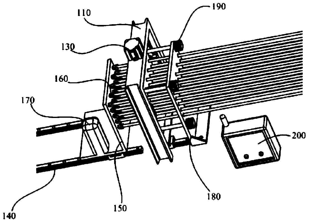
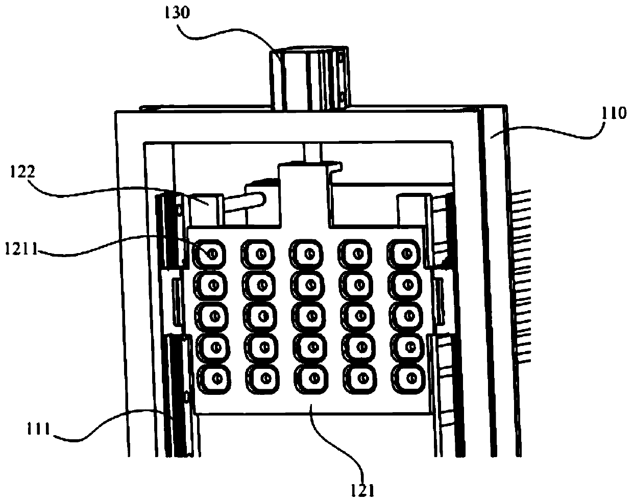
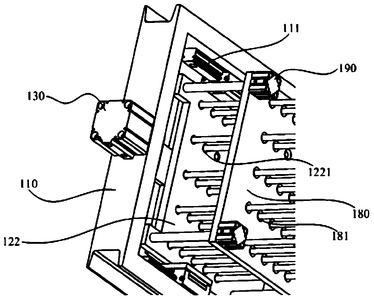
[0021] In view of the prior art, in the cutting process of the heat-shrinkable tube, due to the manual cutting, the cutting efficiency is low, and it is difficult to ensure the accuracy of the cutting length and other technical problems. The invention designs a clamping device and a staggered cutting device for simultaneously clamping and positioning multiple pipes, and cooperates with a control system to effectively improve the efficiency and quality of pipe cutting and realize the automatic operation of cutting.

[0022] In order to more clearly illustrate the technical solutions in the embodiments of the present invention or the prior art, the following will briefly introduce the drawings that need to be used in the description of the embodiments or the prior art. Obviously, the accompanying drawings in the following description are only These are some embodiments of the present invention. Those skilled in the art can also obtain other drawings based on these drawings withou...


PUM


Abstract

The invention discloses a heat shrinkage tube cutting device. The device comprises a knife rest, a cutter arranged on the knife rest, a first driving device connected with the cutter, a rail, a clamping jaw fixing plate connected with the rail, a clamping jaw arranged on the clamping jaw fixing plate, and a motor fixedly connected with the clamping jaw.

Description

technical field [0001] The invention relates to the technical field of polymer pipe manufacture, and in particular to a heat-shrinkable pipe cutting device. Background technique [0002] With the continuous improvement of the performance of polymer materials, the maturity of processing technology and the continuous decline of costs, heat shrinkable sleeves made of polymer materials are widely used in automotive wiring harnesses, electronics, mechanical wiring harnesses and other fields, replacing the original PVC. And metal sheath products, becoming the most widely used wire harness sheath products in the market. [0003] With the vigorous development of the heat-shrinkable tubing industry, the functional requirements of its related supporting equipment are getting higher and higher, and the requirements for the efficiency and precision of heat-shrinkable tubing cutting are also getting higher and higher. During the cutting process of the heat-shrinkable tube, one of the pr...

Claims


Application Information

Patent Timeline
Patent Type & Authority Patents(China)
IPC IPC(8): B26D1/06B26D5/12B26D7/02B26D7/26B26D5/00B26D7/06
Inventor 姚兴磊周金亮黎晨谭林林
Owner SHANGHAI CHANGYUAN ELECTRONICS MATERIAL
Learn More