
Cutting device with moving head

A technology of moving head and workbench, which is applied in metal processing and other directions, can solve the problems of low production efficiency and high energy consumption, and achieve the effects of improving production efficiency, saving punching time, and safe and convenient operation

Inactive Publication Date: 2017-05-10
YANCHENG CITY LONG XIANG MACHINERY MFG PLANT
View PDF5 Cites 0 Cited by
  • Summary
  • Abstract
  • Description
  • Claims
  • Application Information

AI Technical Summary

Problems solved by technology

[0002] The cutting machine is used in the process of sandpaper processing; when the existing cutting machine is used to form the sandpaper, the feeding mechanism needs to carry out a corresponding feeding every time the sandpaper is punched, the production efficiency is not high, and the energy consumption is relatively large

Method used


Image

  • Cutting device with moving head

Examples


Embodiment Construction

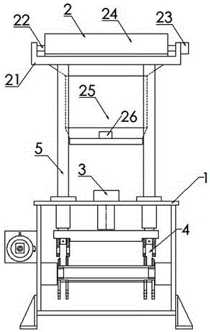
[0010] As shown in Fig. 1, a cutting device with a moving head is composed of a workbench 1 and a moving indenter part 2. The workbench 1 is provided with an oil cylinder device 3 and a balance shaft connected to the oil cylinder device 3. The rod part 4, the column 5 connected with the balance shaft connecting rod part 4, the moving pressure head part 2 is connected on the workbench 1 through the column 5; the oil cylinder device 3 drives the moving pressure head part 2 to press down against the The material is punched; the moving head part 2 consists of an upper platen 21, a lead screw 22 set on the top of the upper platen 21, a servo motor II23 connected to the lead screw 22, and a moving part set on the lead screw 22. The head slide rail 24, the moving head 25 connected on the moving head slide rail 24 and the sensor 26 arranged on the moving head 25 are composed; the moving head 25 is controlled by the servo motor II 23 to move left and right, and is sensed by the sensor 2...


PUM


Abstract

The invention discloses a cutting device with a moving head. The cutting device is composed of a workbench (1) and a moving press head component (2), wherein an oil cylinder device (3) is arranged on the workbench (1), and the oil cylinder device (3) drives the moving press head component (2) to press downwards to cut materials on the workbench (1). The cutting device is characterized in that the moving press head component (2) is composed of an upper press plate (21), a lead screw (22) arranged at the top end of the upper press plate (21), a servo motor II (23) connected to the lead screw (22), a moving head slide rail (24) arranged on the lead screw (22), the moving head (25) connected to the moving head slide rail (24) and a sensor (26) arranged on the moving head (25); and the moving head (25) is controlled to move left and right through the servo motor II (23). According to the cutting device disclosed by the invention, one-time material feeding and many-time cutting are realized, thus the production efficiency is greatly increased.

Description

technical field [0001] The invention relates to the technical field of sandpaper cutting, in particular to a cutting device with a moving head. Background technique [0002] The cutting machine is used in the process of sandpaper processing; when the existing cutting machine is used to form the sandpaper, the feeding mechanism needs to carry out a corresponding feeding every time the sandpaper is punched, the production efficiency is not high, and the energy consumption is relatively large . Contents of the invention [0003] In view of the above deficiencies, the object of the present invention is to provide a cutting device with a moving head, which can punch the material on the surface of the worktable by controlling the moving head part through the oil cylinder device, and reset the moving head part after punching , the servo motor II on the moving head part controls the moving head to move to the set position, the sensor senses and transmits information, and the oil ...

Claims


Application Information

Patent Timeline
Patent Type & Authority Applications(China)
IPC IPC(8): B26D1/08B26D5/06B26D5/12B26D7/22
CPCB26D1/085B26D5/06B26D5/12B26D7/22
Inventor 戴荣祥戴永俊
Owner YANCHENG CITY LONG XIANG MACHINERY MFG PLANT
Learn More