
Onboard control system of high-speed maglev train

A control system and technology for maglev trains, applied in the field of control systems between rails and trains, can solve problems such as the complexity of the synchronous linear motor control system, the difficulty of avoiding two-car collision accidents, and the restriction of the development of maglev trains. method and computing equipment, eliminating the need for intermediate transfer control links, and the effect of simple structure

Inactive Publication Date: 2017-05-10
DALIAN WHIM SCI & TECH LTD CO
View PDF5 Cites 7 Cited by
  • Summary
  • Abstract
  • Description
  • Claims
  • Application Information

AI Technical Summary

Problems solved by technology

[0003] The typical electromagnetic levitation trains that have been put into commercial operation are Germany’s EMS electromagnetic levitation system and Japan’s EDS superconducting electric levitation train, both of which use synchronous linear motor traction drive technology, and the control system of synchronous linear motors that control train running is relatively complicated , the obvious problem is that two trains in the same driving section can only be controlled by the same control system, and it is impossible for two trains that are about to collide to avoid running in opposite directions. It is difficult to avoid two-vehicle collisions in the same driving section
The power system and control system that control the train's running are on the track. The train and the track need to collect sensors for the relative displacement between the train and the track. It also requires a set of very complex algorithms and computing equipment, and even requires remote control technology to transmit the train. The communication signals with the control system on the track make the structure of the control system very complex, and there are too many control links, which makes the reliability fragile. The complex control system restricts the development of maglev trains

Method used


Image

  • Onboard control system of high-speed maglev train
  • Onboard control system of high-speed maglev train
  • Onboard control system of high-speed maglev train

Examples


Embodiment Construction

[0033] The present invention is described in further detail now in conjunction with accompanying drawing.

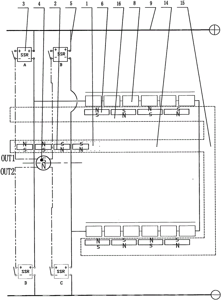
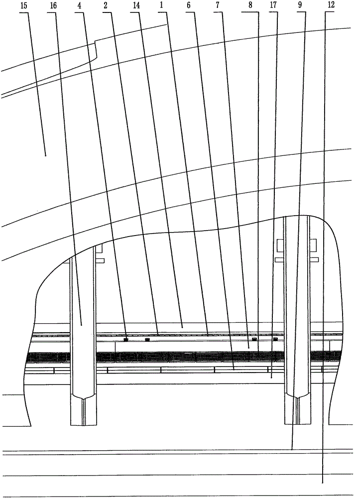
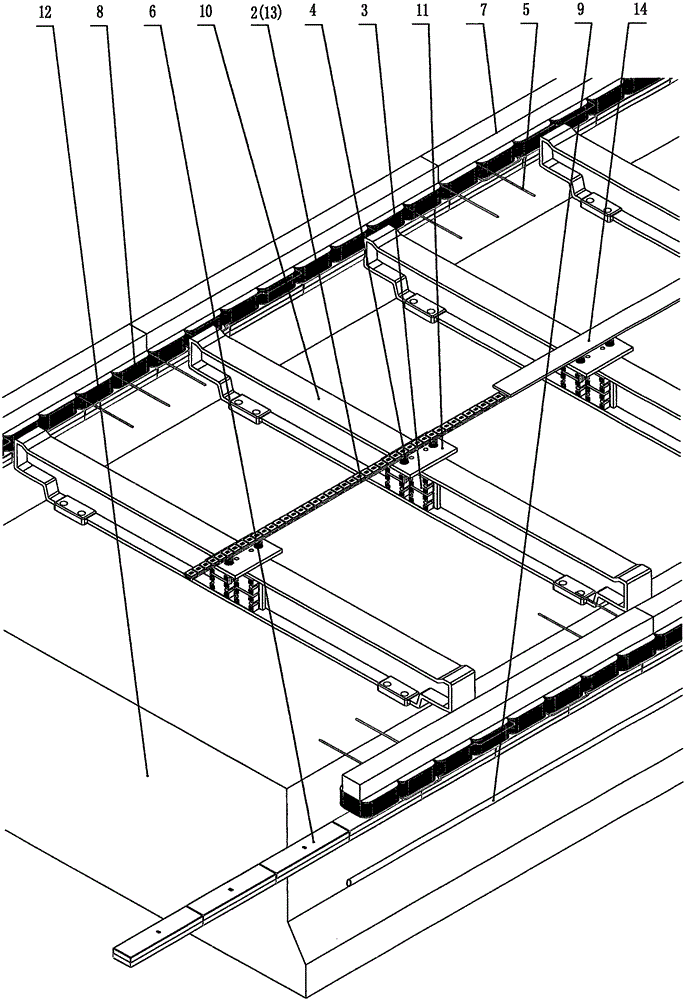
[0034] Such as figure 1 As shown, the working principle of the vehicle-mounted control system 1 of the present invention is disclosed. Main wires 9 are arranged on both sides of the track. The main wire 9 on one side is the positive pole of the power supply, and the main wire on one side is the negative pole of the power supply. The track is provided with a fixed drive coil 8, and the bottom of the drive coil 8 is provided with a traction permanent magnet 6 at a certain gap, and the traction permanent magnet 6 is fixedly connected to the bottom of the train, and the fixed drive coil 8 and the traction permanent magnet 6 constitute a linear motor. Each group of driving coils 8 is composed of several sub-coils, which are connected in series to form a group of driving coils 8, and the two ends of each group of driving coils 8 are connected with two solid state relays 3 to b...


PUM


Abstract

The present invention provides an onboard control system of a high-speed maglev train. The onboard control system of the high-speed maglev train is characterized in that drive coils and Hall sensor proximity switches 4 are provided on a track, the drive coils 8 are controlled by the Hall sensor proximity switches to be connected or disconnected, the bottom of the train is provided with onboard permanent magnets or vehicle control solenoid coils as the onboard control system at the positions corresponding to the Hall sensor proximity switches, the onboard control system can directly control the drive coils in a contactless way through the Hall sensor proximity switches, so that the train can directly control the drive coils on the track, the defect that substations are required to be arranged at intervals in the traditional control system can be overcome, and the control system is more simple and reliable in structure.

Description

[0001] Technical field [0002] The invention relates to the technical field of rail transportation, in particular to a control system for a maglev train and a track, in particular to a control system between a track and a train driven by a linear motor. Background technique [0003] The typical electromagnetic levitation trains that have been put into commercial operation are Germany’s EMS electromagnetic levitation system and Japan’s EDS superconducting electric levitation train, both of which use synchronous linear motor traction drive technology, and the control system of synchronous linear motors that control train running is relatively complicated , the obvious problem is that two trains in the same driving section can only be controlled by the same control system, and it is impossible for two trains that are about to collide to avoid running in opposite directions. It is difficult to avoid two-vehicle collision accidents when arriving at the same driving section. The p...

Claims


Application Information

Patent Timeline
Patent Type & Authority Applications(China)
IPC IPC(8): B60L13/06
CPCB61B13/08E01B25/30Y02T10/72
Inventor 刘忠臣
Owner DALIAN WHIM SCI & TECH LTD CO
Learn More