Supercharge Your Innovation With Domain-Expert AI Agents!

Vehicle engine room pipeline layout structure and vehicle

A technology for arranging structure and cabin, which is applied in the directions of vehicle components, circuits or fluid pipelines, transportation and packaging, etc., which can solve the problem that the engine room pipeline structure cannot be systematically arranged, the engine room pipeline structure layout is inconvenient, and the pipeline maintenance and replacement are difficult, etc. problems, to achieve the effect of easy maintenance and identification, easy layout positioning structure, easy layout and installation

Active Publication Date: 2019-05-07
GREAT WALL MOTOR CO LTD
View PDF6 Cites 0 Cited by
  • Summary
  • Abstract
  • Description
  • Claims
  • Application Information

AI Technical Summary

Problems solved by technology

Due to functional requirements, the pipelines in the engine room have many types, inconsistent specifications and relatively concentrated, which leads to inconvenience in the structural layout of the pipelines in the engine room
The existing pipeline layout structure of the engine room often sacrifices the pipeline layout space in order to meet the layout conditions of the engine room, which makes the utilization rate of the engine room low, and the pipeline structure of the engine room cannot be arranged systematically, resulting in repeated changes in the later stage
In addition, the pipeline layout structure of the existing engine room still has the problem of difficulty in pipeline maintenance and replacement during the use of the vehicle, which is also not conducive to the after-sales work.

Method used


Image

  • Vehicle engine room pipeline layout structure and vehicle

Examples


Embodiment 1

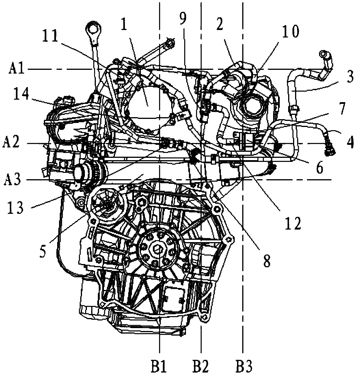
[0027] This embodiment relates to a pipeline arrangement structure in the engine room of a vehicle, such as figure 1 As shown in , it includes a desorption pipe assembly 2 , a vacuum booster pipe assembly 3 , an intercooler pipe assembly 5 and an oil inlet pipe assembly 4 respectively connected to the engine main body 1 . The pipeline layout structure of the vehicle cabin also includes a carbon canister solenoid valve 6 arranged in parallel on the desorption pipe assembly 2 , and an unshown air filter arranged on the engine main body 1 . In this embodiment, along the height direction of the vehicle, the connection point between the desorption pipe assembly 2 and the air filter is also figure 1 The second connection point 10, the connection point between the desorption tube assembly 2 and the canister solenoid valve 6 is the fourth connection point 12, the connection point between the vacuum booster tube assembly 3 and the engine main body 1 is the fifth connection point 13, a...

Embodiment 2

[0035] This embodiment relates to a vehicle, which includes an engine main body arranged in the engine room, a desorption pipe assembly connected to the engine main body, a vacuum booster pipe assembly, an intercooler pipe assembly, and an oil inlet pipe assembly; The canister solenoid valve installed in parallel on the desorption pipe assembly, and the air filter installed on the engine main body, and the desorption pipe assembly, vacuum booster pipe assembly, intercooler pipe assembly, oil inlet pipe assembly and Between the carbon canister solenoid valve and the air filter, the vehicle cabin pipeline layout structure as described in Embodiment 1 is arranged at the engine main body.

[0036] In the vehicle of this embodiment, through the structural arrangement between the assemblies as described in Embodiment 1, the pipelines of each assembly can be arranged in sections, which is convenient for arranging the positioning structure, and also facilitates the later maintenance of...


PUM


Abstract

The invention provides a vehicle cabin piping layout structure. The structure comprises a desorption pipe assembly, a vacuum hose assembly, an intercooler pipe assembly and an oil inlet pipe assembly which are connected to an engine body separately; the structure further comprises a carbon tank solenoid valve arranged on the desorption pipe assembly in parallel and an air filter arranged on the engine body. The invention further provides a vehicle set according to the vehicle cabin piping layout structure. According to the vehicle cabin piping layout structure, by means of arrangement of positions of connection points of all assemblies, piping can be arranged in a sectional mode, and the positioning structure can be arranged conveniently. The piping is arranged in an X-shaped mode in the vehicle width direction so as to play a role in vibration cushion and torque attenuation. Meanwhile, by means of arrangement of all connecting points, all the piping can be vertically arranged in the vehicle length direction, maintenance identification of the piping in the later period can be convenient, and integrity and uniformity of the whole piping structure can be achieved.

Description

technical field [0001] The invention relates to the technical field of automobiles, in particular to a pipeline arrangement structure in a vehicle cabin. The invention also relates to a vehicle provided with such a vehicle cabin pipeline arrangement structure. Background technique [0002] The structural layout of the vehicle cabin pipeline is an important part of the vehicle development process, and its layout is directly related to the performance of each component, and will also affect the subsequent optimization work. Due to functional requirements, the pipelines in the engine room have many types, inconsistent specifications and relatively concentrated, which leads to inconvenience in the structural layout of the pipelines in the engine room. The existing pipeline layout structure of the engine room often sacrifices the pipeline layout space in order to meet the layout conditions of the engine room, which makes the utilization rate of the engine room low, and the pipel...

Claims


Application Information

Patent Timeline
Patent Type & Authority Patents(China)
IPC IPC(8): B60R16/08
CPCB60R16/08
Inventor 李麒裴玉李晓娟
Owner GREAT WALL MOTOR CO LTD
Features
  • R&D
  • Intellectual Property
  • Life Sciences
  • Materials
  • Tech Scout
  • Unparalleled Data Quality
  • Higher Quality Content
  • 60% Fewer Hallucinations
Learn More