
Secondary main beam composite beam bridge using prefabricated composite bridge deck slabs and construction method of secondary main beam composite beam bridge

A composite bridge and panel technology, which is applied in bridges, bridge parts, bridge construction, etc., can solve the problems of bridge decks such as self-heavy weight, low comprehensive cost, and small transverse span, so as to reduce project cost, reduce project cost, and prefabricate high effect

Active Publication Date: 2017-05-10
湖南省交通水利建设集团有限公司 +1
View PDF7 Cites 19 Cited by
  • Summary
  • Abstract
  • Description
  • Claims
  • Application Information

AI Technical Summary

Problems solved by technology

The composite girder bridge with few main girders adopts the above-mentioned prefabricated composite bridge deck structure with high bearing capacity, reasonable stress and light weight, and is suitable for roads and cities with medium span (40-60m) and wide bridge width (10-18m). , The bridge with fewer main girders (2-3), effectively solves the problems of the existing bridge deck, such as heavy weight, small transverse span, and easy cracking; it adopts modular prefabrication, simple structure, short construction period, and comprehensive cost Low

Method used


Image

  • Secondary main beam composite beam bridge using prefabricated composite bridge deck slabs and construction method of secondary main beam composite beam bridge
  • Secondary main beam composite beam bridge using prefabricated composite bridge deck slabs and construction method of secondary main beam composite beam bridge
  • Secondary main beam composite beam bridge using prefabricated composite bridge deck slabs and construction method of secondary main beam composite beam bridge

Examples


Embodiment

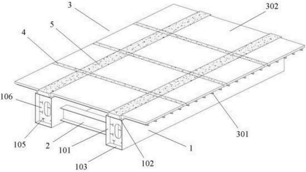
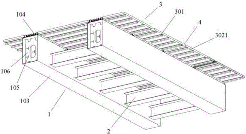
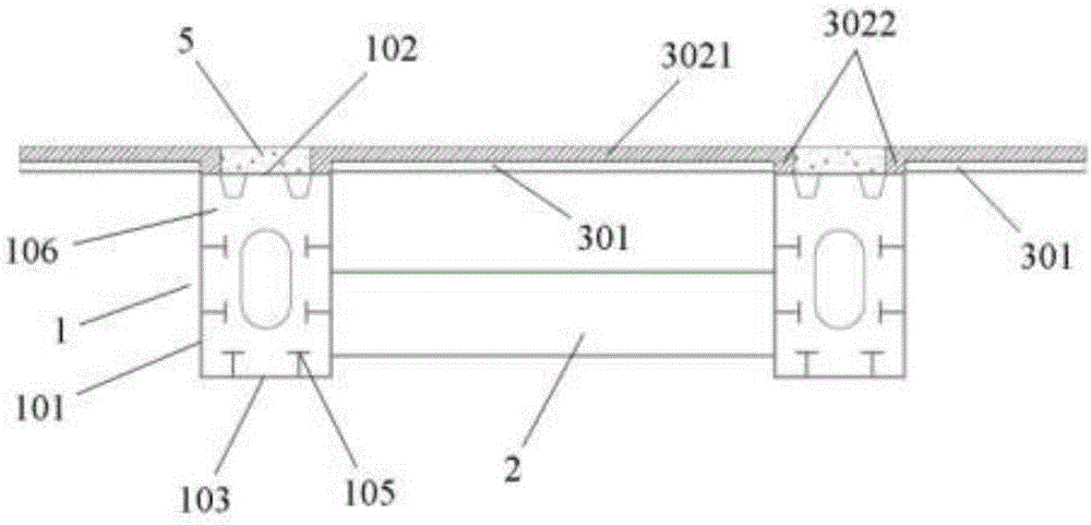
[0040] The present invention is an embodiment of a composite girder bridge with few main girders that adopts prefabricated composite bridge decks. The composite girder bridge with few main girders is mainly suitable for composite girder bridges with medium span (40-60m), wide bridge width (10-18m) and few main girders (2-3) in highways and cities. The structure of the composite girder bridge with few main girders is as follows: Figure 1 to Figure 7 shown by Figure 1 to Figure 7 It can be seen that it mainly includes a plurality of steel box girders 1 arranged along the bridge direction, and a plurality of prefabricated composite bridge decks 3 are erected on the steel box girders 1 , and the steel box girders 1 are connected by steel cross beams 2 . Transverse wet joints 4 are formed at intervals between adjacent prefabricated composite bridge decks 3 . The prefabricated composite bridge deck 3 includes a plurality of section steels 301 arranged in the transverse bridge di...


PUM


Abstract

The invention discloses a secondary main beam composite beam bridge using prefabricated composite bridge deck slabs and a construction method of the secondary main beam composite beam bridge. The secondary main beam composite beam bridge includes steel box beams, steel cross beams and the prefabricated composite bridge deck slabs, a horizontal wet joint is formed between every two adjacent bridge deck slabs, the prefabricated composite bridge deck slabs include a plurality of pieces of structural steel and prefabricated concrete layers cast on the structural steel, the bottom of the structural steel is welded to the steel box beams, longitudinal wet joints are formed in the prefabricated composite bridge deck slabs and in the range of the top of the steel box beams, a plurality of through holes are formed in the structural steel and in the range of the longitudinal wet joints, perforated steel bars connected with the structural steel pass through the through holes, and vertical and horizontal direction steel bar meshes are arranged in the prefabricated concrete layers, stretch out of the prefabricated range of the prefabricated composite bridge deck slabs and are connected with the perforated steel bars; wet joint concrete is cast in situ in the horizontal wet joints and the longitudinal wet joints. The secondary main beam composite beam bridge is light in dead weight, large in bearing capacity, reasonable in loading, good in integrality and large in adaptation width.

Description

technical field [0001] The invention relates to the technical field of composite structure bridges, in particular to a composite girder bridge with few main girders and a construction method thereof using a prefabricated composite bridge deck. Background technique [0002] At present, with the development and practice of bridge engineering, more and more engineers and technicians have reached the following consensus on the application of small and medium-span bridges: The technology is mature and the cost is relatively low, but the construction period is too long, the self-heaviness is heavy, and the durability is poor; the steel girder bridge can greatly shorten the construction period and reduce the structural self-weight, but the cost is high, and the defects of the orthogonal special-shaped steel bridge deck are prominent; in recent years The rapidly developing steel plate-concrete composite girder bridge fully utilizes the characteristics of the material, not only is th...

Claims


Application Information

Patent Timeline
Patent Type & Authority Applications(China)
IPC IPC(8): E01D1/00E01D2/04E01D19/00
CPCE01D1/00E01D2/04E01D19/00
Inventor 陈洪伟彭江辉向建军李瑜刘榕张贵明杨沪湘王甜崔剑峰王卿周旋
Owner 湖南省交通水利建设集团有限公司
Learn More