Water-sand separation building arrangement form suitable for curve chute spillway

A technology for separation of water and sand, spillway, applied in construction, water conservancy projects, marine engineering and other directions, can solve problems such as deterioration, spillway overflow boundary damage, and potential safety hazards in operation, and achieve the effect of reducing impact and smooth connection.

Inactive Publication Date: 2017-05-10
SICHUAN UNIV
View PDF3 Cites 6 Cited by
  • Summary
  • Abstract
  • Description
  • Claims
  • Application Information

AI Technical Summary

Problems solved by technology

If the cavitation of water flow and the damage forms such as sediment particle impact and abrasion continue to superimpose, the damage of the overflow boundary of the spillway will be worse
The above-mentioned damage patterns will not only cause greater operational safety hazards, but also increase the difficulty and cost of maintenance in the later stages of the project.

Method used


Image

  • Water-sand separation building arrangement form suitable for curve chute spillway
  • Water-sand separation building arrangement form suitable for curve chute spillway
  • Water-sand separation building arrangement form suitable for curve chute spillway

Examples


Embodiment Construction

[0087] The specific implementation of the present invention is not limited to the form in the embodiment, according to the disclosed content of the present invention, those skilled in the art can also adopt other specific ways to implement, therefore, the example can not be understood as the only possible implementation of the present invention detailed description.

[0088] Engineering example

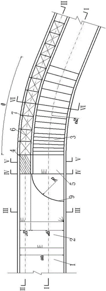
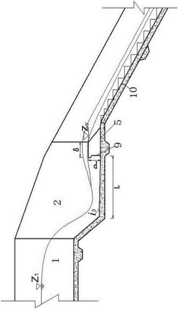
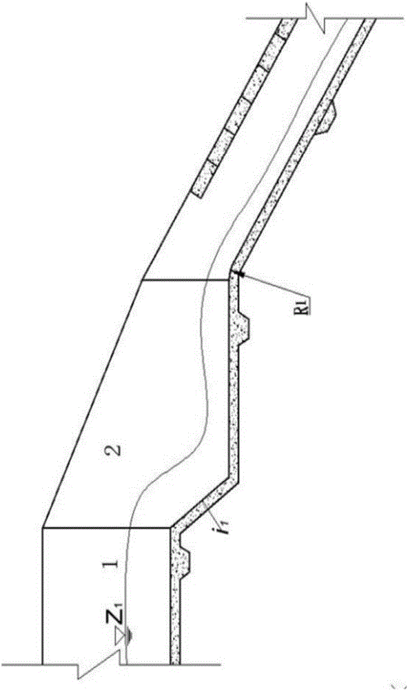
[0089] The construction stockyard of a hydropower station is located in a debris flow ditch, and the source of large and granular sediment in the upstream is relatively large. Under the condition of heavy rain runoff, a large amount of sediment will be released. A retaining dam is installed in the upstream of the material yard to intercept the incoming flow and sand from the upstream. A drainage tunnel is used in front of the retaining dam to guide the upstream water and sand to a suitable location, and then the steep groove spillway is used to discharge it into the river channel. Th...


PUM


Abstract

The invention discloses a water-sand separation building arrangement form suitable for a curve chute spillway. A water-sand separation building comprises a sand collection pool with the upstream end connected with an incoming flow spillway and the curve chute spillway located at the downstream end of the sand collection pool. The curve chute spillway is composed of parallelly arranged flow passing channels and a sand discharge channel. An inlet base plate of the sand discharge channel is smoothly connected with a base plate of the sand collection pool. A curve section flow channel base plate of the sand discharge channel is an inwards-inclining continuous base plate with the high outer wall side and the low inner wall side. The flow passing channels are connected with the sand collection pool through an overflow weir. The curve section flow channel base plate of the flow passing channel is a base plate of a step structure. The upstream face of the overflow weir is an arc face and forms a sand guide wall for guiding large particles and granular silt in water flow into the sand discharge channel. By adoption of the water-sand separation building arrangement form, the granular silt in the high-flow-speed and high-sand-content water flow can be effectively separated from the water flow, and the purposes of safely discharging sand, decreasing a protective range, lowering the maintenance cost, improving project operation safety and the like are achieved.

Description

technical field [0001] The invention relates to water conservancy and hydropower projects and disaster prevention and mitigation projects, and is especially suitable for implementing water and sand separation in steep groove spillways with bends. Background technique [0002] At present, all kinds of flood control, water diversion, irrigation, disaster prevention and mitigation projects built in mountainous rivers must be equipped with sand prevention measures. Sand settling tanks are one of the most commonly used measures. Hydraulic structures with a relatively small sediment probability mainly include linear grit chambers, curved grit chambers, swirl type grit chambers, inclined plate type grit chambers, and funnel type grit chambers. The basic principles of low water velocity in the sand pool and the circulation of the bend realize the separation of water and sand, and there is almost no damage to the flow boundary. [0003] In water conservancy and hydropower projects o...

Claims


Application Information

Patent Timeline
Patent Type & Authority Applications(China)
IPC IPC(8): E02B8/02
CPCE02B8/023
Inventor 马旭东聂锐华夏雪平刘兴年贾栖
Owner SICHUAN UNIV
Why Eureka
Try Eureka