Counter-force structure of static load test and static load test system

A static load test and connection structure technology, which is applied in the direction of basic structure engineering, basic structure test, construction, etc., can solve the problems of inapplicability and safety of the static load test reaction force structure, and achieve flexible layout, good safety and easy installation. The effect of convenient process

Active Publication Date: 2017-05-10
中冶沈勘工程技术有限公司
View PDF7 Cites 9 Cited by
  • Summary
  • Abstract
  • Description
  • Claims
  • Application Information

AI Technical Summary

Problems solved by technology

[0006] The present invention aims to provide a static load test reaction force structure to solve the problem that the...

Method used


Image

  • Counter-force structure of static load test and static load test system
  • Counter-force structure of static load test and static load test system
  • Counter-force structure of static load test and static load test system

Examples


Embodiment

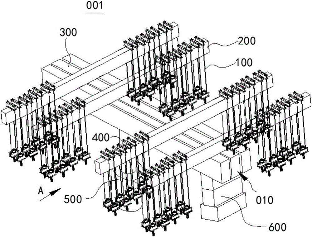
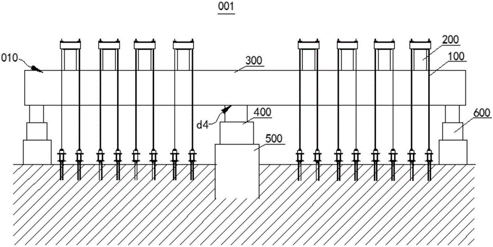
[0060] figure 1 is a schematic structural view of the static load test system 001 in the embodiment of the present invention; figure 2 yes figure 1 A view from direction A. Please refer to figure 1 , figure 2 , the static load test system 001 in this embodiment includes a test pile 500 and a static load test reaction force structure 010 for providing a reaction force to the test pile 500 .

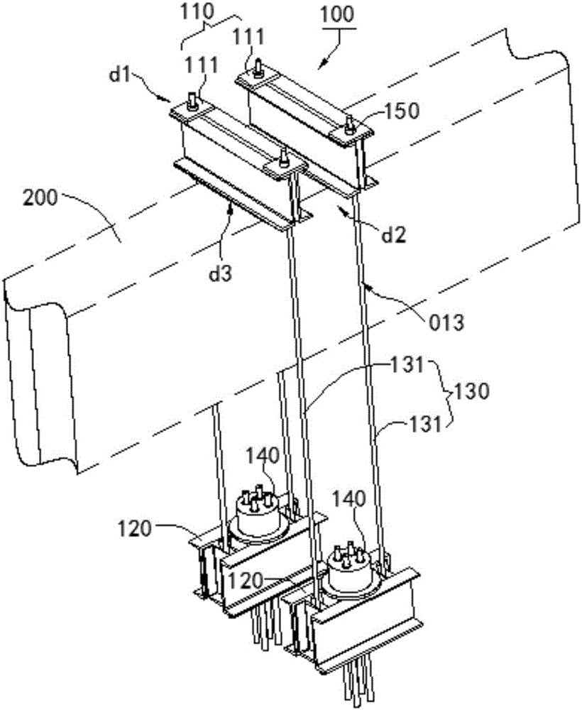
[0061] Among them, the static load test reaction force structure 010 includes a jack 400, a main beam 300 supported on the upper end of the jack 400, a number of secondary beams 200 respectively pressed on the two ends of the upper end surface of the main beam 300, and a plurality of secondary beams 200 along the length of each secondary beam 200. The anchor rod connection structures 100 are distributed in directions and located on both sides of the main beam 300 .

[0062] The upper end of the bolt connection structure 100 is connected to the secondary beam 200 , and the lower end ...


PUM


Abstract

The invention relates to the field of constructional engineering, aims to solve the problem that in the prior art, a counter-force structure of a static load test is not suitable or is poor in safety in the mounting process, and provides a counter-force structure of the static load test and a static load test system provided with the counter-force structure of the static load test. The counter-force structure of the static load test comprises a jack, a primary beam which is supported at the upper end of the jack, a plurality of secondary beams which separately press the two ends of the upper end surface of the primary beam and a plurality of anchor rod connecting structures which are separately distributed along the length directions of the secondary beams and are located on two sides of the primary beam. The upper ends of the anchor rod connecting structures are connected to the secondary beams, and the lower ends of the anchor rod connecting structures are fixedly arranged for limiting upward displacement of the secondary beams. The jack is supported in a supporting position between the two ends of the lower end surface of the primary beam, and the secondary beams on two sides are separately located on two sides of the supporting device. The counter-force structure of the static load test provided by the invention has the beneficial effects that the counter-force structure of the static load test is flexibly arranged, can be suitable for different pile base design forms and provide different counter-forces, and is convenient in mounting process and good in safety.

Description

technical field [0001] The invention relates to the field of construction engineering, in particular to a static load test reaction force structure. The invention also relates to a static load test system equipped with the static load test reaction force structure. Background technique [0002] The quality of foundation pile engineering mainly depends on two factors, namely bearing capacity and pile body quality. Accurate testing of pile bearing capacity plays a pivotal role in the foundation design and even the superstructure design of various buildings. [0003] Static load test is a test to test the bearing capacity of construction engineering piles. The static load test of the pile is to use the settlement of a fixed period of time as the stability standard. By applying different loads, and then measuring the settlement of the pile body through the displacement meter erected on the top of the pile, the relationship between the load and the settlement can be obtained. ...

Claims


Application Information

Patent Timeline
IPC IPC(8): E02D33/00
CPCE02D33/00
Inventor 孙传印辛利伍贺振宇李炳海刘伟张笑凡董天文吕志浩钱同庆丁晓明杨立鹏
Owner 中冶沈勘工程技术有限公司
Why Eureka
Try Eureka