Reinforced concrete column beam anti-shock joint

A reinforced concrete, column beam technology, applied in earthquake resistance, building types, buildings, etc., can solve problems such as overall structural failure, vulnerable column ends, and potential safety hazards.

Inactive Publication Date: 2017-05-10
QINGDAO TECHNOLOGICAL UNIVERSITY
View PDF0 Cites 4 Cited by
  • Summary
  • Abstract
  • Description
  • Claims
  • Application Information

AI Technical Summary

Problems solved by technology

However, under the actual earthquake, the column ends are very vulnerable to damage, and the design goal of "strong

Method used


Image

  • Reinforced concrete column beam anti-shock joint
  • Reinforced concrete column beam anti-shock joint
  • Reinforced concrete column beam anti-shock joint

Examples


Example Embodiment

[0029] The present invention will be further explained below in conjunction with the drawings:

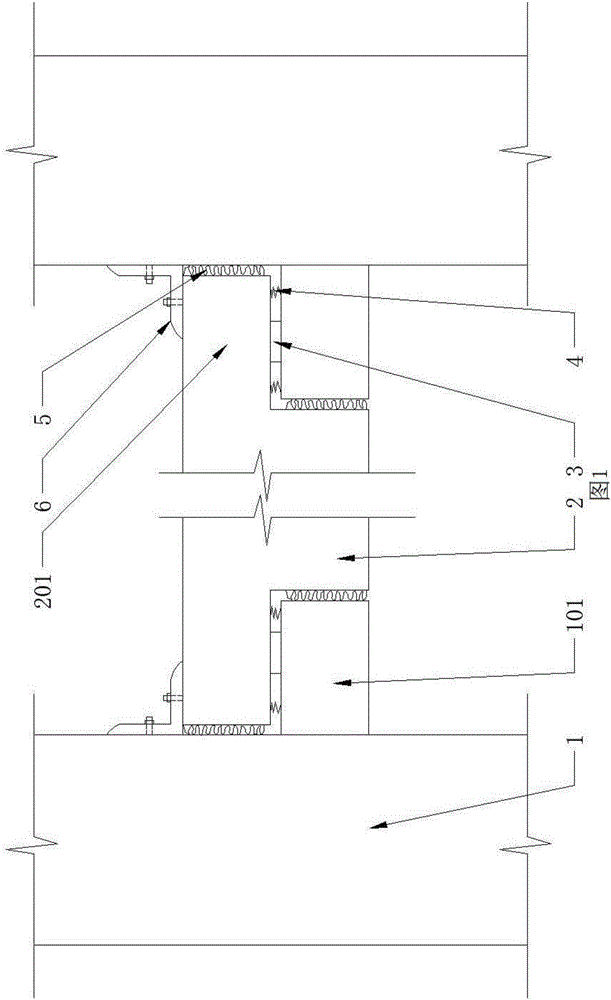
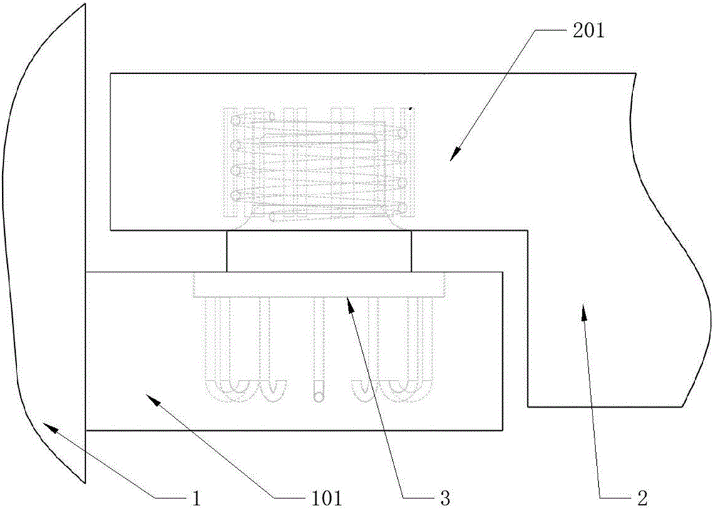
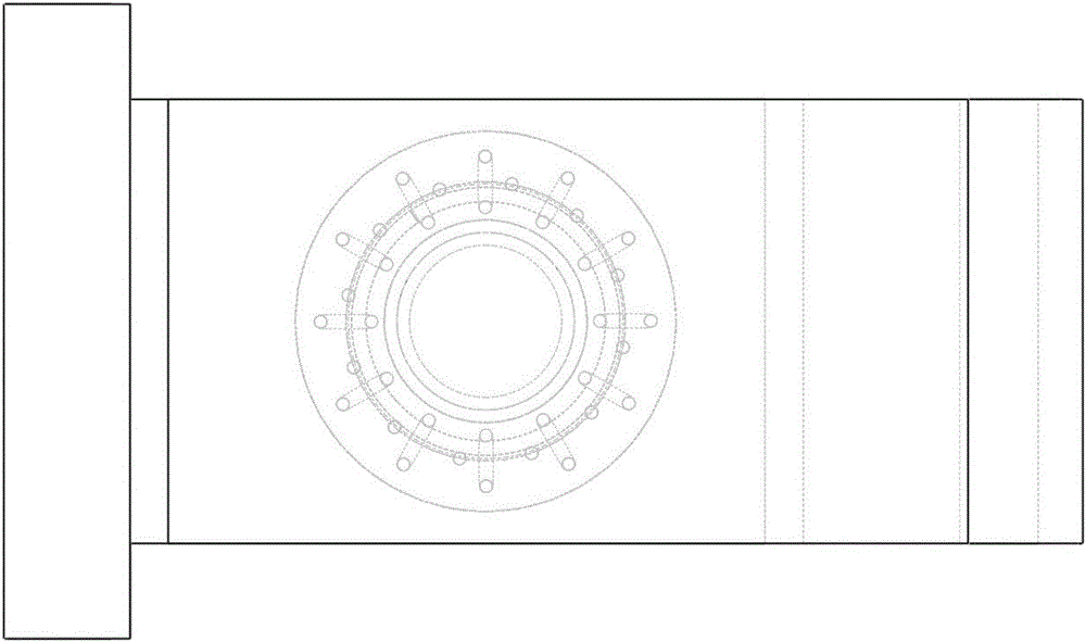
[0030] Such as Figure 1 to Figure 11 As shown, the reinforced concrete column beam seismic joint of the present invention includes a frame column 1, the frame column 1 extends outward to form a corbel 101, and the two ends of the frame beam 2 between the frame columns 1 extend outward to form a The protrusion 201 that matches the corbel 101, the protrusion 201 is provided with a limiting hole 8, and the limiting hole 8 is matched with the limiting platform 3 provided on the corbel 101; preferably, the limiting hole 8 The position table 3 includes a limit post 304 that matches with the limit hole 8. An inner corner 303 that matches the outer corner 801 is arranged between the limit post 304 and the base 302, and the bottom of the base 302 is fixedly connected There are multiple hooked steel bars 301; there is ample space for rotation between the top of the limit post 304 and the limi...


PUM

PropertyMeasurementUnit
Diameteraaaaaaaaaa
Diameteraaaaaaaaaa

Abstract

The invention relates to a building structure joint, in particular to a reinforced concrete column beam anti-shock joint. The joint comprises frame columns, the frame columns extend outward to form brackets, the two ends of a frame beam between the frame columns extend outward to form protruding parts matched with the brackets, limiting holes are formed in the protruding parts, and the limiting holes are matched with limiting tables on the brackets. According to the reinforced concrete column beam anti-shock joint, the frame columns and the frame beam are connected in a split mode, during earthquakes, the frame beam and the beam columns rotate relative to each other along an inner circular bead and an outer circular bead under cooperation of the limiting holes and the limiting columns to form a plastic hinge at the beam end, the frame columns can be effectively protected, and collapse and failure of a structure are prevented.

Description

Technical field [0001] The invention relates to a building structure node, in particular to a reinforced concrete column beam seismic node. Background technique [0002] In civil engineering, frame beams refer to beams connected to frame columns at both ends. At present, there are two main types of reinforced concrete frame structures. One is the cast-in-place reinforced concrete frame structure, where the frame beams and frame columns are cast in place to form a unified whole; the other is the assembled integral frame structure, where the frame beams and frame columns are prefabricated parts. , Connected into a whole by welding or bolting. Under the action of vertical load, the frame beam bears the load and transmits it to the frame column, which is an important component of the structure; under the action of horizontal load, it is hoped that plastic hinges will appear at the end of the beam in the design, and the seismic energy will be dissipated through the rotation of the pl...

Claims


Application Information

Patent Timeline
IPC IPC(8): E04B1/20E04B1/58E04B1/98E04H9/02
CPCE04B1/20E04B1/58E04H9/021
Inventor 宁宁于德湖张春巍蒋姗
Owner QINGDAO TECHNOLOGICAL UNIVERSITY
Why Eureka
Try Eureka