Self-suction electric control low pressure fuel counter for internal combustion engine

A low-pressure fuel and measuring device technology, which is applied in the direction of machines/engines, liquid fuel feeders, and charging systems, can solve the problems of complex structure, poor hydraulic stability, and weak reliability of high-pressure generating devices, and achieve improved process Performance and reliability, good hydraulic stability, simplified design

Active Publication Date: 2017-05-10
TSINGHUA UNIV
View PDF6 Cites 2 Cited by
  • Summary
  • Abstract
  • Description
  • Claims
  • Application Information

AI Technical Summary

Problems solved by technology

[0002] In the existing internal combustion engine technology, the type of low-pressure fuel delivered to the high-pressure generating device, one (such as a single-cylinder diesel engine) is sucked from the fuel tank by the suction function of the high-pressure generating device itself; The multi-cylinder diesel engine with electronically controlled unit combined pump) adopts an independent single-delivery oil delivery pump, and the supply volume is completely dependent on the hydraulic characteristics that change with the speed; The type, such as the common rail technology multi-cylinder machine, still follows the traditional technical route of the oil delivery pump with an independent single delivery function, and arranges the pressure limiting function and the quantitative control function in the design of the high pressure generating device, resulting in Complex, poor manufacturability, relatively weak reliability, poor hydraulic stability
Especially it is difficult to test the sealing and hydraulic characteristics of the low-pressure system alone

Method used


Image

  • Self-suction electric control low pressure fuel counter for internal combustion engine
  • Self-suction electric control low pressure fuel counter for internal combustion engine
  • Self-suction electric control low pressure fuel counter for internal combustion engine

Examples


Embodiment Construction

[0023] Preferred embodiments of the present invention will be further described below with reference to the accompanying drawings. It should be understood, however, that these descriptions are exemplary only and are not intended to limit the scope of the invention.

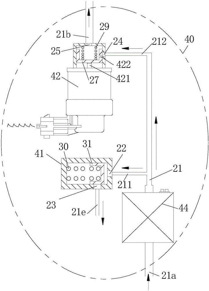
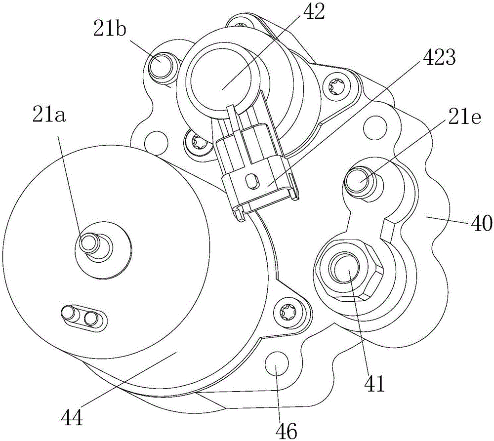
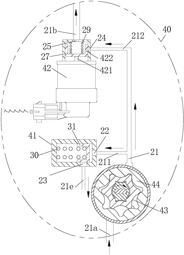
[0024] figure 1 A self-priming electronically controlled low-pressure fuel meter for a single-cylinder diesel engine according to the first embodiment is exemplified. The electronically controlled low pressure fuel gauge includes a gauge housing 40 . The electric low-pressure fuel delivery pump 44 integrated on the meter housing 40 pumps the diesel oil from the fuel tank (not shown) of the internal combustion engine (sometimes referred to as "engine") into the meter housing after boosting the pressure from the fuel inlet channel 21a The fuel main channel 21 in the body 40.

[0025] A pressure limiting valve 41 and an electronically controlled metering valve 42 are arranged in parallel on the fuel main passage 2...


PUM


Abstract

The invention relates to a self-suction electric control low pressure fuel counter for an internal combustion engine. The self-suction electric control low pressure fuel counter is provided with a counter shell (40), a pressure limiting valve (41), an electric control metering valve (42) and a low pressure fuel conveying pump (44). The electric control metering valve is controlled by an electronic control unit. Fuel sucked by the low pressure fuel conveying pump (44) from an oil tank of the internal combustion engine is controlled by the pressure limiting valve (41) to be supplied to a fuel high pressure generation device of the internal combustion engine through the electric control metering valve (42) in a fixed quantity and time mode. The electric control low pressure fuel counter is an independent device, the pressure limiting valve, the electric control metering valve and the low pressure fuel conveying pump are integrated on the counter shell, the counter can be installed at the corresponding position of the internal combustion engine or installed on a fuel high pressure generation device. According to the electric control low pressure fuel counter, the design of the fuel high pressure generation device is simplified to the maximum extent, and the good hydraulic stability is provided for a fuel injection device of the internal combustion engine.

Description

technical field [0001] This invention relates to components for internal combustion engines, and more particularly to self-priming, electronically controlled low pressure fuel gauges for internal combustion engines. Background technique [0002] In the existing internal combustion engine technology, the type of low-pressure fuel delivered to the high-pressure generating device, one (such as a single-cylinder diesel engine) is sucked from the fuel tank by the suction function of the high-pressure generating device itself; The multi-cylinder diesel engine with electronically controlled unit combined pump) adopts an independent single-delivery oil delivery pump, and the supply volume is completely dependent on the hydraulic characteristics that change with the speed; The type, such as the common rail technology multi-cylinder machine, still follows the traditional technical route of the oil delivery pump with an independent single delivery function, and arranges the pressure li...

Claims


Application Information

Patent Timeline
Patent Type & Authority Applications(China)
IPC IPC(8): F02M37/00F02M37/04
CPCF02M37/0011F02M37/0023F02M37/0029F02M37/04
Inventor 张可谢之峰牟学利周明
Owner TSINGHUA UNIV
Why Eureka
Try Eureka