A wave generator

A technology of wave power generation and power generation unit, which is applied in the directions of ocean energy power generation, engine components, machines/engines, etc., can solve the problem of less utilization of wave energy, and achieve the effect of improving utilization rate and collection efficiency

Active Publication Date: 2020-01-17
李广明
View PDF5 Cites 0 Cited by
  • Summary
  • Abstract
  • Description
  • Claims
  • Application Information

AI Technical Summary

Problems solved by technology

[0002] At present, with the gradual depletion of non-renewable energy sources such as coal, oil, and natural gas, the development of new energy sources has gradually become the focus of people. Among them, wave energy reserves are very rich, but people's utilization of wave energy is still relatively small, and there is great development. potential

Method used


Image

  • A wave generator
  • A wave generator
  • A wave generator

Examples


Embodiment 2

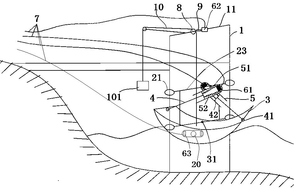
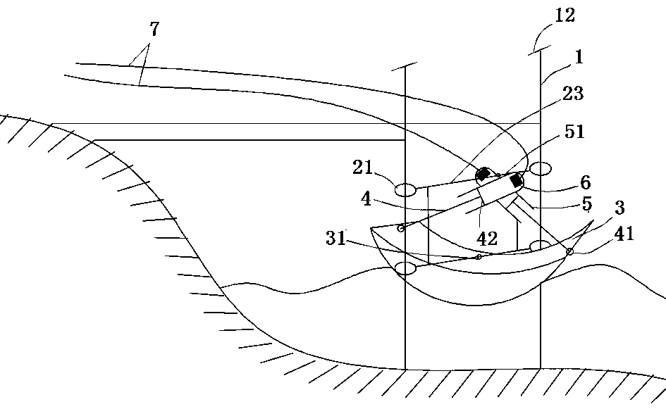
[0052] Embodiment 2: as figure 2 As shown, the main difference between this embodiment and Embodiment 1 is that no power rope 10, overrunning clutch 8, crankshaft 9, counterweight 101 and other devices for collecting the energy of the wave lifting movement are no longer set in this embodiment, but basically A stop bar 12 should be provided on the top of the frame 1, so that the sliding collar 21 can not slip off from the vertical bar of the base frame 1. Present embodiment is also no longer provided with straight cylinder, striking member 20 and piezoelectric generator 63, and return spring 52 is not provided between piston 42 and outer cylinder body 5 cylinder bottoms, also can arrange return spring 52 certainly, and present embodiment utilizes The structure should be as simple as possible to obtain as much energy as possible from the waves, because the energy of the waves is mainly the energy that pushes the floating body 3 to swing. The purpose of the device in this embodi...

Embodiment 3

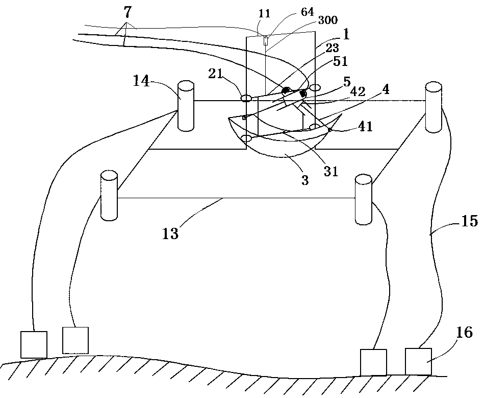
[0053] Embodiment 3: as image 3 As shown, the main difference between this embodiment and Embodiment 2 is that the base frame 1 of this embodiment is not directly fixed on the coast, but is fixed on a floating support frame 13, the support frame 13 is rectangular, and the middle of the rectangle Two rigid rods fixed to the bottom of the base frame 1 are arranged, and the space between the two rigid rods allows the floating body 3 to contact seawater, and the floating body 3 can swing freely when waves hit the floating body 3 . Four corners of the support frame 13 are respectively fixed with supporting floating bodies 14 to float the support frame 13 and the base frame 1 on the support frame 13 . The supporting floating body 14 is a cylindrical hollow sealed shell structure, and the length is extended vertically when in use, so that the anti-tipping performance of the device is better, safer and more stable. The four corners of the support frame 13 are also connected with sta...

Embodiment 4

[0054] Embodiment 4: as Figure 5 As shown, the main difference from Embodiment 1 is that a cylinder is hinged on the crossbar 11 of the base frame 1, a linear generator 64 is arranged in the cylinder, and a straight rod 300 is welded on the upper crossbeam of the mounting frame 2. , the straight rod 300 extends towards the direction of the cylinder, and its other end is connected with the moving parts of the linear generator 64. When the mounting frame 2 slides up and down under the drive of the floating body 3, the straight rod 300 can drive the linear generator 64 to generate electricity. Realize the further utilization of wave energy. Of course, the cylinder and the straight rod 300 here can also exchange installation positions, that is, the straight rod 300 is fixed on the base frame 1, and the cylinder where the linear generator 64 is located is installed on the mounting frame 2; the straight rod 300 and the mounting frame 2 1. As long as one of the installation methods...


PUM


Abstract

The invention relates to a wave power generation device which comprises a base frame, wherein a mounting frame is arranged on the base frame, the mounting frame is articulated with a floating body which moves with waves and swings around an articulation axis, and at least one power generation unit is also mounted on the mounting frame; the power generation unit comprises a push rod, and a push rod coupling part is arranged at one end of the push rod; the power generation unit further comprises a coupler in guidance movement match with the push rod coupling part in the length direction of the push rod, one of the coupler and the push rod is articulated at the position of the floating body, which is located on one side of the articulation axis of the floating body, the other one of the coupler and the push rod is articulated with the mounting frame, an articulation point of the coupler, an articulation point of the push rod and an articulation point of the floating body form three vertexes of a triangle, and the coupler and the push rod move in a reciprocating manner when the floating body swings around the articulation axis; the power generation unit further comprises a main power generator arranged on the coupler and / or the push rod coupling part, and the main power generator is a piezoelectric power generator or a linear power generator. According to the wave power generation device provided by the invention, wave energy can be effectively converted and collected, and the collection efficiency is high.

Description

technical field [0001] The invention relates to a wave power generating device. Background technique [0002] At present, with the gradual depletion of non-renewable energy sources such as coal, oil, and natural gas, the development of new energy sources has gradually become the focus of people. Among them, wave energy reserves are very rich, but people's utilization of wave energy is still relatively small, and there is great development. potential. [0003] Wave energy refers to the energy generated by the fluctuation of the liquid surface. The energy of wave energy is affected by the wave height, period and width of the facing slope. When the wave fluctuates, its wave height, period and height of the facing slope are unstable, and the tide The influence of tsunami and tsunami makes the collection and utilization of wave energy more difficult, and the collection of wave energy has become a very important link in the utilization of wave energy. Contents of the invention ...

Claims


Application Information

Patent Timeline
Patent Type & Authority Patents(China)
IPC IPC(8): F03B13/18
CPCF03B13/18F05B2220/706F05B2220/707F05B2220/709Y02E10/30
Inventor 李广明李一帆李玉玺
Owner 李广明
Why Eureka
Try Eureka