A mechanical clutch device for a drive shaft

A technology of clutch device and transmission shaft, which is applied in the direction of transmission parts, mechanically driven clutches, and clutches that mesh with each other, which can solve problems such as oil leakage or noise pollution, malfunction, slipping, etc., and achieve short adjustment time, convenient clutch, easy-to-handle effects

Active Publication Date: 2019-02-01
BAOTOU ENG & RES CORP OF IRON & STEEL IND CHINA METALLURGY CONSTR GROUP BERIS
View PDF5 Cites 0 Cited by
  • Summary
  • Abstract
  • Description
  • Claims
  • Application Information

AI Technical Summary

Problems solved by technology

When overloaded, the clutch device will slip, and the strict synchronization of the transmission shaft cannot be guaranteed
During the operation of the electromagnetic clutch device, due to the vibration or the sensitivity of the electrical detection element, it may cause malfunction and affect the normal operation of the equipment.
[0004] The hydraulic and pneumatic clutch devices need to be equipped with an oil supply or air supply system, which may also cause oil leakage or noise pollution.

Method used


Image

  • A mechanical clutch device for a drive shaft
  • A mechanical clutch device for a drive shaft

Examples


Embodiment Construction

[0025] In order to better understand the purpose, structure and function of the present invention, a mechanical clutch device for a transmission shaft of the present invention will be described in further detail with reference to the accompanying drawings.

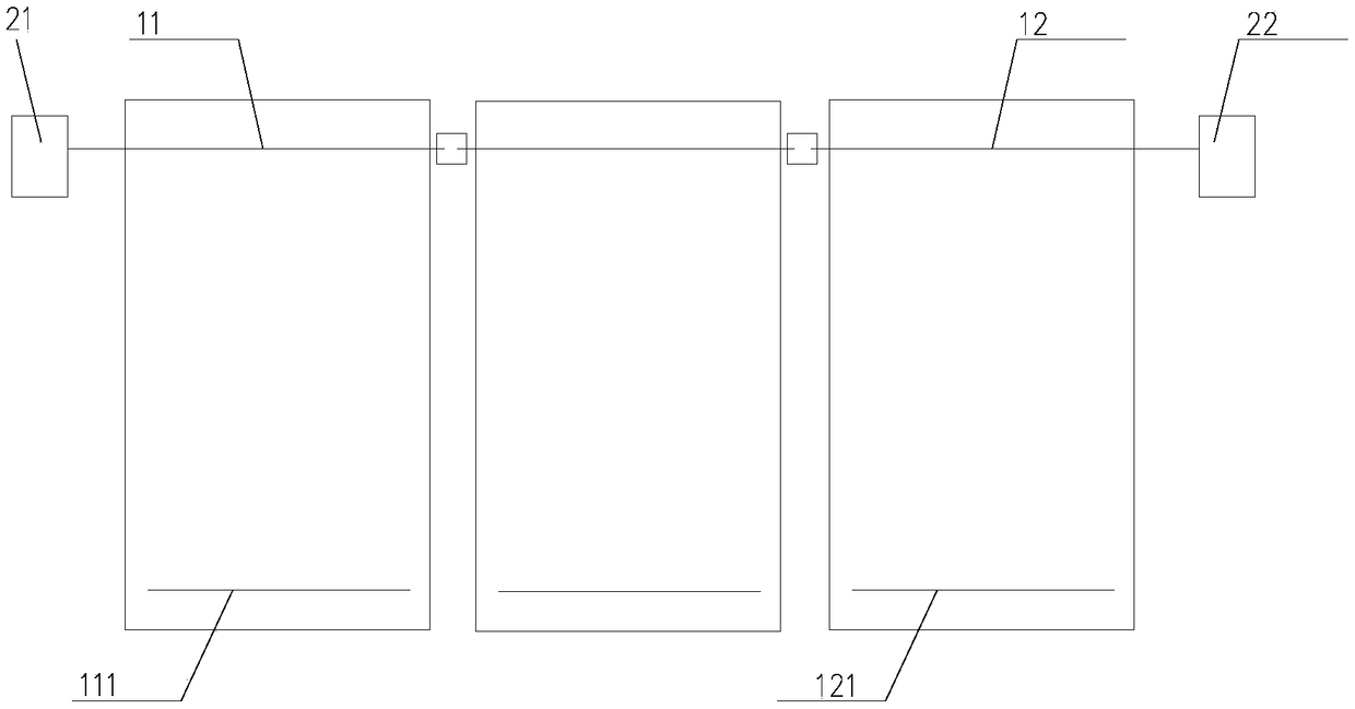
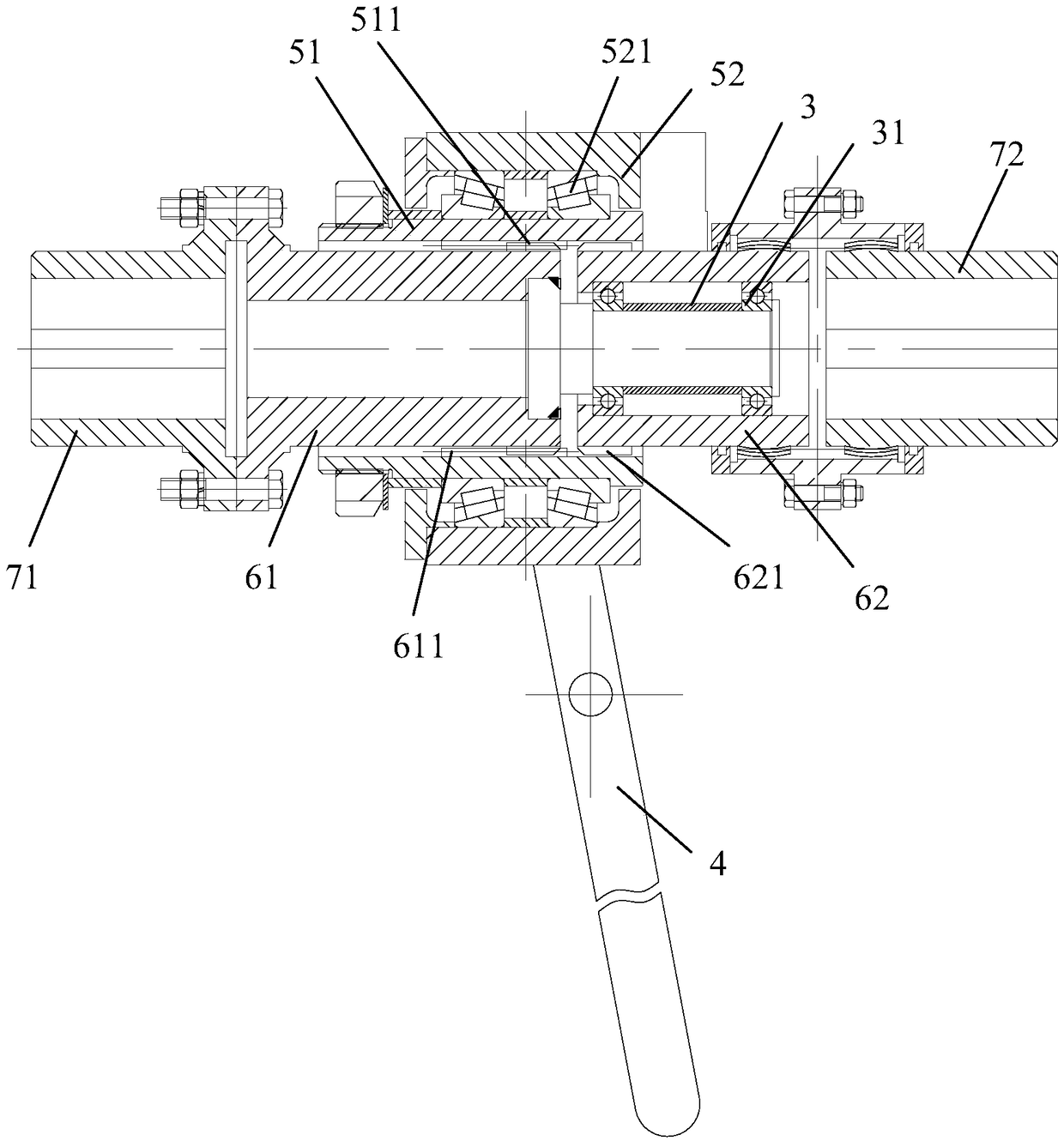
[0026] Such as figure 1 with figure 2 As shown, it is shown as a mechanical clutch device of a transmission shaft of the present invention, which is used to connect and disconnect the transmission shafts in multiple transmission platforms (movable platforms or lateral transport equipment), specifically, on the transmission platform Both are provided with a transmission shaft, and a first power source 21 and a second power source 22 for transmitting power are provided on both sides of the transmission platform. The first power source 21 and the second power source 22 are connected by a transmission on the adjacent transmission platform. The shafts are connected together, and the power is transmitted through the transmission a...


PUM


Abstract

The invention discloses a mechanical type separation-and-union device for transmission shafts. The separation-and-union device is arranged between the transmission shafts of adjacent transmission platforms and comprises a first gear sleeve half (61), a second gear sleeve half (62) and a separation-and-union assembly. The first gear sleeve half (61) is connected with the first transmission shaft on the transmission platform arranged at one side through a coupling half (71), and the first transmission shaft drives the first gear sleeve half (61) to rotate. The second gear sleeve half (62) is arranged beside the first gear sleeve half (61) and connected with the second transmission shaft on the second transmission platform arranged at the other side through a crown-gear coupling (72), and the second transmission shaft drives the second gear sleeve half (62) to rotate. The separation-and-union assembly is arranged outside the first gear sleeve half (61) and the second gear sleeve half (62) and controlled to be connected with and separated from the first gear sleeve half (61) and the second gear sleeve half (62) so that the transmission platforms arranged at the two sides can be driven by the first transmission shaft and the second transmission shaft to perform synchronous movement or separate movement. According to the mechanical type separation-and-union device, the transmission shafts on the transmission platforms are connected or separated, and the effect that multiple transmission platforms are driven can be achieved.

Description

Technical field [0001] The invention relates to a clutch device, in particular to a mechanical clutch device of a transmission shaft. Background technique [0002] At present, the clutch device is divided into mechanical, electromagnetic, hydraulic and pneumatic types. Among them, the mechanical clutch has a jaw type, a friction type, etc. The jaw type clutch device can strictly guarantee two drive shafts. Synchronization, but in the case of excessive torque or large vibration, the teeth will be damaged or skipped. When the diameter of the transmission shaft is large, the clutch device is correspondingly larger, which is difficult to install and adjust, and takes a long time. [0003] The current friction clutch device relies on the friction force between the friction parts to transmit torque, and friction heat is generated during the coupling process of the friction parts, and heat dissipation measures are required. When overloaded, the clutch device will slip, which cannot guara...

Claims


Application Information

Patent Timeline
Patent Type & Authority Patents(China)
IPC IPC(8): F16H57/023F16D11/04
CPCF16D11/04F16H57/023
Inventor 赵忠凯郭榕伟
Owner BAOTOU ENG & RES CORP OF IRON & STEEL IND CHINA METALLURGY CONSTR GROUP BERIS
Why Eureka
Try Eureka