Rotary speed reducer and rotary speed reducer for walking

A technology of rotary reducer and cooling mechanism, which is applied in the direction of mechanical equipment, transmission parts, gear transmission, etc., can solve the problem that the rotary reducer cannot be used as a travel reducer, and achieve the purpose of improving thermal balance stability and realizing high temperature use Effect

Pending Publication Date: 2017-05-10
SUOTE TRANSMISSION EQUIP
View PDF7 Cites 0 Cited by
  • Summary
  • Abstract
  • Description
  • Claims
  • Application Information

AI Technical Summary

Problems solved by technology

[0007] The purpose of the present invention is to provide a rotary reducer and a rotary reducer for walking...

Method used


Image

  • Rotary speed reducer and rotary speed reducer for walking
  • Rotary speed reducer and rotary speed reducer for walking
  • Rotary speed reducer and rotary speed reducer for walking

Examples


Embodiment Construction

[0038] It should be noted that, in the case of no conflict, the embodiments of the present invention and the features in the embodiments can be combined with each other. The present invention will be described in detail below with reference to the accompanying drawings and examples.

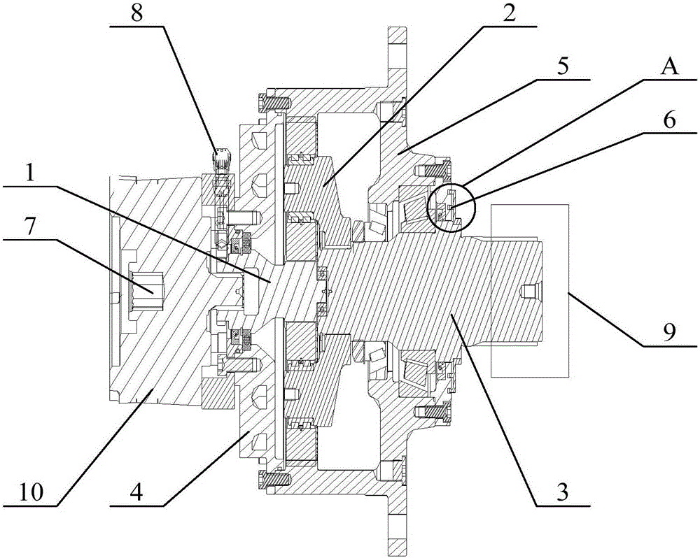
[0039] figure 1 Schematic diagram of the structure of the rotary reducer provided by the embodiment of the present invention.

[0040] like figure 1 As shown, the embodiment of the present invention provides a rotary reducer, including: an input spline sleeve 1, which is connected to an output spline shaft 3 through a planetary mechanism assembly 2; Cooling mechanism 4. The cooling mechanism 4 is used for forced cooling of the lubricating oil in the casing of the slewing reducer.

[0041] Compared with the prior art, the rotary reducer described in the embodiment of the present invention has the following advantages:

[0042] In the rotary speed reducer provided by the embodiment of the prese...


PUM


Abstract

The invention discloses a rotary speed reducer and a rotary speed reducer for walking, and relates to the technical field of speed reducers. The rotary speed reducer comprises an input spline sleeve connected with an output spline shaft through a planet mechanism assembly, wherein a cooling mechanism is arranged near the input spline sleeve; and the cooling mechanism is used for forcedly refrigerating lubricating oil in a box body of the rotary speed reducer. The technical problem that a rotary speed reducer in the prior art cannot serve as a walking speed reducer can be solved through the rotary speed reducer.

Description

technical field [0001] The invention relates to the technical field of reducers, in particular to a rotary reducer and a rotary reducer for walking. Background technique [0002] The reducer plays the role of matching the speed and transmitting torque between the prime mover and the working machine or the actuator. The reducer is a relatively precise machine. The purpose of using it is to reduce the speed and increase the torque. The reducer is an independent component composed of gear transmission, worm transmission, and gear-worm transmission enclosed in a rigid shell. It is often used as a reduction transmission device between the original moving part and the working machine. [0003] At present, the reducer can include a rotary reducer and a travel reducer. Among them, the slewing reducer is a full-circle slewing deceleration transmission mechanism that integrates the driving power source. It uses the slewing bearing as the transmission follower and the attachment of th...

Claims


Application Information

Patent Timeline
IPC IPC(8): F16H57/04F16H57/029F16H57/10F16H1/28
CPCF16H1/28F16H57/029F16H57/0413F16H57/0417F16H57/10
Inventor 张金标肖军宝贾广利王珏
Owner SUOTE TRANSMISSION EQUIP
Why Eureka
Try Eureka