Carbon steel ball valve

A ball valve, carbon steel technology, applied in the valve details, valve device, valve shell structure and other directions, can solve the problems of hidden leakage, high processing and assembly requirements, matching tolerances, etc., to achieve energy-saving processing efficiency, good anti-leakage, not easy shaking effect

Active Publication Date: 2018-08-24
LIANGGANG VALVE GRP
View PDF5 Cites 0 Cited by
  • Summary
  • Abstract
  • Description
  • Claims
  • Application Information

AI Technical Summary

Problems solved by technology

[0005] 1. Since the main body of the ball valve and the end cover are threaded, there is a fit tolerance between the two. Some of them use an external gasket structure, but there is a hidden danger of leakage; while the overall welding has seams, so the strength is not enough, and there may be leakage, that is, two leak-proof performance is poor
[0006] 2. Due to the high temperature generated during the overall welding may affect the parts installed in the main body of the ball valve, it is easy to deform or damage the internal parts and cause the seal to fail
[0007] 3. Due to the fit gap between the main body of the ball valve and the internal parts, in order to make the ball valve have a good seal, the processing and assembly requirements for the parts are very high, which also makes the cost high; there are also ball valves that adjust the end cover and Adjust the gap between the main bodies of the ball valve, but the adjustment range is not much, the effect is not good, and there may be leakage

Method used


Image

  • Carbon steel ball valve
  • Carbon steel ball valve
  • Carbon steel ball valve

Examples


Embodiment 1

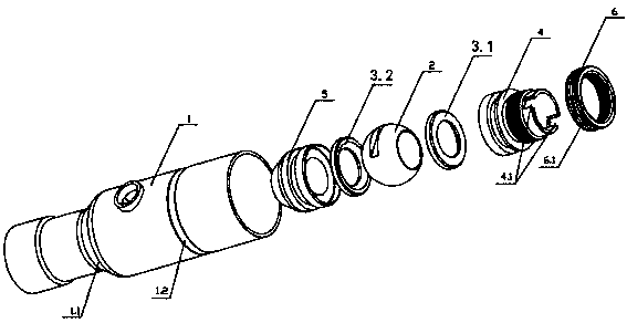
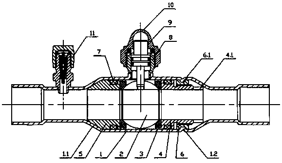
[0027] Such as figure 1 , figure 2 As shown, the ball valve of the present invention includes a ball valve main body 1, a ball 2, a first seal 3.1, a first inner plug body 4, and a second inner plug body 5; the ball 2 passes through the first seal 3.1 and the second inner plug body on both sides. The seal 3.2 is positioned in the inner cavity of the ball valve main body 1, and one end of the first inner plug body 4 and the second inner plug body 5 are both against the corresponding first seal 3.1 and the second seal 3.2, and the first inner plug body 4 Seal between the second inner plug body 5 and the ball valve body 1, that is, a sealing ring 7 is provided between the first inner plug body 4 and the second inner plug body 5 and the ball valve body 1; the pressure relief assembly 11 and the top connecting body 8 are all welded on the main body 1 of the ball valve, the valve stem assembly 9 is set in the top connecting body 8, and the cap 10 is screwed on the top connecting...


PUM


Abstract

The invention discloses a carbon steel ball valve. The other ends of a first inner cock body and a second inner cock body are pressed against an inner wall of a contracting opening of a ball valve body; a plurality of first grooves are formed in end surfaces, close to a ball, of a first seal member and a second seal member; a plurality of second grooves are formed in end surfaces, away from the ball, of the first seal member and the second seal member; first seal strips are arranged in the first grooves; second seal strips are arranged in the second grooves; the first seal strips are pressed against outer peripheries of the first grooves and the ball; and the second seal strips are pressed against outer peripheries of the second grooves and the ball. The ball valve body is formed integrally, fit tolerance and seams can be avoided, leakage can be avoided, and the leakage-proof performance is excellent. The ball valve body is integrally formed by a copper tube without cutting or casting, materials can be saved, energy can be saved, and the processing efficiency is high; and an adjustment device is arranged in the ball valve body, and the leakage-proof performance of the ball valve will not be influenced.

Description

technical field [0001] The invention belongs to the field of valve devices, in particular to a carbon steel ball valve. Background technique [0002] At present, ball valves are widely used in petroleum refining, long-distance pipelines, chemical industry, papermaking, pharmaceuticals, water conservancy, electric power, municipal, steel and other industries, and occupy a pivotal position in the national economy. It has the action of rotating 90 degrees, the cock body is ball body , with a circular through-hole or channel passing through its axis. [0003] Ball valves are mainly used in pipelines cut off , Distributing and changing the flow direction of the medium, it only needs to rotate 90 degrees and a small rotational torque to close tightly. [0004] The current ball valve structure generally includes a ball valve body, a ball, two seals, an end connector, a cap, a top connector, a valve stem assembly, and a liquid filling assembly; the ball is positioned in the in...

Claims


Application Information

Patent Timeline
Patent Type & Authority Patents(China)
IPC IPC(8): F16K5/06F16K5/08F16K27/06
CPCF16K5/0663F16K5/08F16K27/067
Inventor 王甲林
Owner LIANGGANG VALVE GRP
Why Eureka
Try Eureka