
Self-stabilization single-face thin film restrictor with prepressure adjusting function

A membrane restrictor and restrictor technology, which is applied to valve devices, safety valves, functional valve types, etc. Not in the design state, the preload is not adjustable, etc.

Inactive Publication Date: 2017-05-10
QILU UNIV OF TECH +1
View PDF6 Cites 4 Cited by
  • Summary
  • Abstract
  • Description
  • Claims
  • Application Information

AI Technical Summary

Problems solved by technology

[0003] At present, the status quo of the preloaded single-sided film restrictor is that its preload is not adjustable during use, its application range is limited, and it cannot adapt to the requirements of changing working conditions. This not only makes the throttling ratio not in the ideal design state, but also And reduce the load-bearing stiffness, and in worse cases, it will cause the static pressure system to fail
At the same time, during the working process of the existing preloaded single-sided film restrictor, it is impossible to adjust the preload of the restrictor itself according to the change of oil supply pressure or load pressure or other working conditions. adapt to
[0004] To sum up, in the prior art, there is still a lack of an effective solution to the problem of the preload adjustment of the single-sided membrane restrictor and the problem that the preload cannot be adapted to the working conditions.

Method used


Image

  • Self-stabilization single-face thin film restrictor with prepressure adjusting function
  • Self-stabilization single-face thin film restrictor with prepressure adjusting function
  • Self-stabilization single-face thin film restrictor with prepressure adjusting function

Examples


Embodiment Construction

[0043] It should be pointed out that the following detailed description is exemplary and intended to provide further explanation to the present application. Unless defined otherwise, all technical and scientific terms used herein have the same meaning as commonly understood by one of ordinary skill in the art to which this application belongs.

[0044] It should be noted that the terminology used here is only for describing specific implementations, and is not intended to limit the exemplary implementations according to the present application. As used herein, unless the context clearly dictates otherwise, the singular is intended to include the plural, and it should also be understood that when the terms "comprising" and / or "comprising" are used in this specification, they mean There are features, steps, operations, means, components and / or combinations thereof.

[0045] As introduced in the background technology, there are problems in the prior art that the preload of the s...


PUM


Abstract

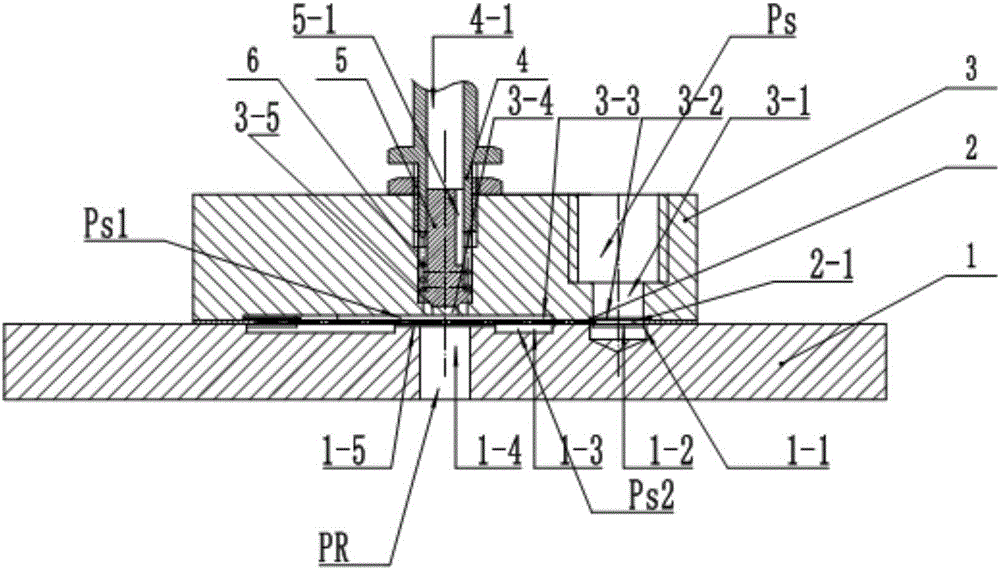
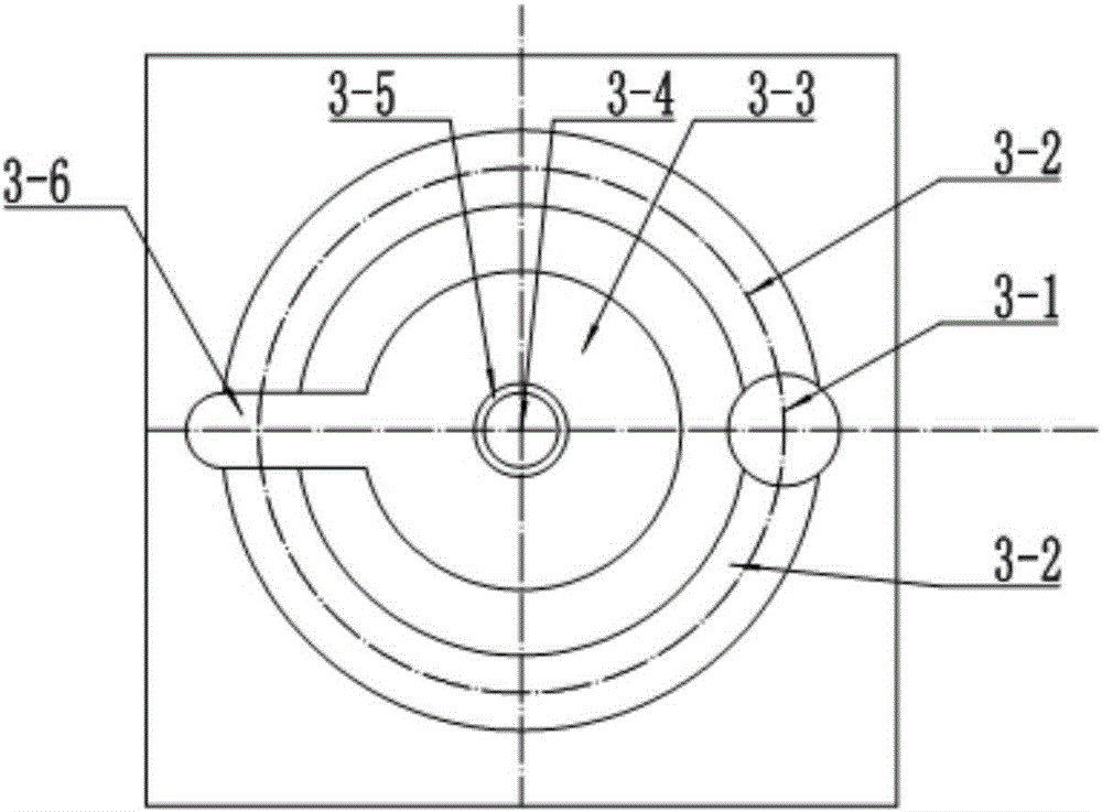
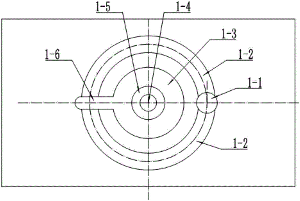
The invention discloses a self-stabilization single-face thin film restrictor with a prepressure adjusting function. The problem of adjusting prepressure of the single-face thin film restrictor and the problem that prepressure cannot adapt to the working condition are solved, the effect of adjusting prepressure of the restrictor is achieved, and therefore the restrictor is capable of meeting the application requirement of working condition changes. Prepressure fluctuation can be automatically stabilized to stably control the throttling gap and realize the ideal throttling ratio. According to the technical scheme, the self-stabilization single-face thin film restrictor comprises an upper valve body and a lower valve body, an elastic thin film is arranged between the upper valve body and the lower valve body, a prepressure cavity is formed between the bottom of the upper valve body and the elastic thin film and communicated with a throttling conical hole, an adjusting stud is arranged in the throttling conical hole, an upper oil outlet hole is formed in the adjusting stud, and a throttling conical valve is arranged in the upper oil outlet hole through an elastic element in a supported mode; a throttling cavity is formed between the bottom of the lower valve body and the elastic thin film, a throttling table is arranged at the top of the lower valve body, and the throttling cavity is communicated with a lower oil outlet hole through a throttling gap between the throttling table and the elastic thin film.

Description

technical field [0001] The invention relates to the technical field of static pressure in precision machinery, in particular to an adjustable pre-pressure self-stabilizing single-sided film restrictor. Background technique [0002] Hydrostatic technology is widely used in precision machinery, and hydrostatic guide rails, hydrostatic bearings, and hydrostatic screw screws are typical application examples. The restrictor is a key component in these static pressure equipment, and its performance has an important influence on these static pressure equipment. Among them, the film throttle is the most widely used one, which is divided into single-sided film throttle and double-sided film throttle. The single-sided film restrictor can adjust the throttling gap by preloading, so as to achieve the ideal throttling effect, and has been paid attention to in recent years. Germany and Taiwan conducted systematic research and application. [0003] At present, the status quo of the prel...

Claims


Application Information

Patent Timeline
Patent Type & Authority Applications(China)
IPC IPC(8): F16K17/00
CPCF16K17/00
Inventor 李春玲路长厚
Owner QILU UNIV OF TECH
Learn More