
Rotary joint for single-point mooring system

A rotary joint and single-point mooring technology, applied in the direction of pipeline system, pipe/pipe joint/pipe fitting, adjustable connection, etc., can solve the problems of shortening life, increasing the gap between upper and lower pipe bodies, and crude oil leakage. , to prolong life and avoid leakage

Active Publication Date: 2017-05-10
WUHAN MARINE MACHINERY PLANT
View PDF7 Cites 6 Cited by
  • Summary
  • Abstract
  • Description
  • Claims
  • Application Information

AI Technical Summary

Problems solved by technology

[0004] In the existing rotary joints, the seal between the upper pipe body and the lower pipe body is usually axially sealed, that is, the sealing ring is arranged on the opposite end faces of the upper pipe body and the lower pipe body. It will float up and down. Since the upper body is supported on the lower body, the seal ring will be repeatedly squeezed during the floating process, resulting in shortened life. There may be a large gap between them, and at the same time, due to the high pressure of crude oil in the rotary joint, the gap between the upper pipe body and the lower pipe body will also increase, so that the crude oil leaks from the gap, and the staff cannot know Whether the sealing ring is invalid and cannot be repaired in time

Method used


Image

  • Rotary joint for single-point mooring system
  • Rotary joint for single-point mooring system
  • Rotary joint for single-point mooring system

Examples


Embodiment Construction

[0023] In order to make the object, technical solution and advantages of the present invention clearer, the implementation manner of the present invention will be further described in detail below in conjunction with the accompanying drawings.

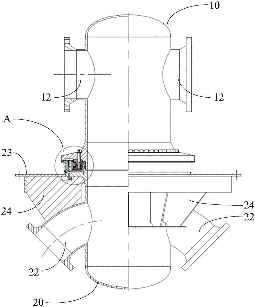
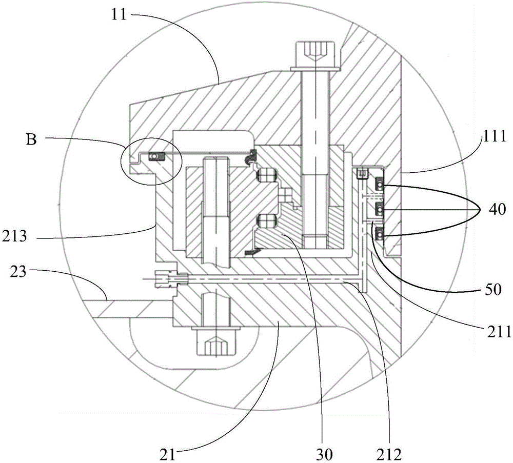
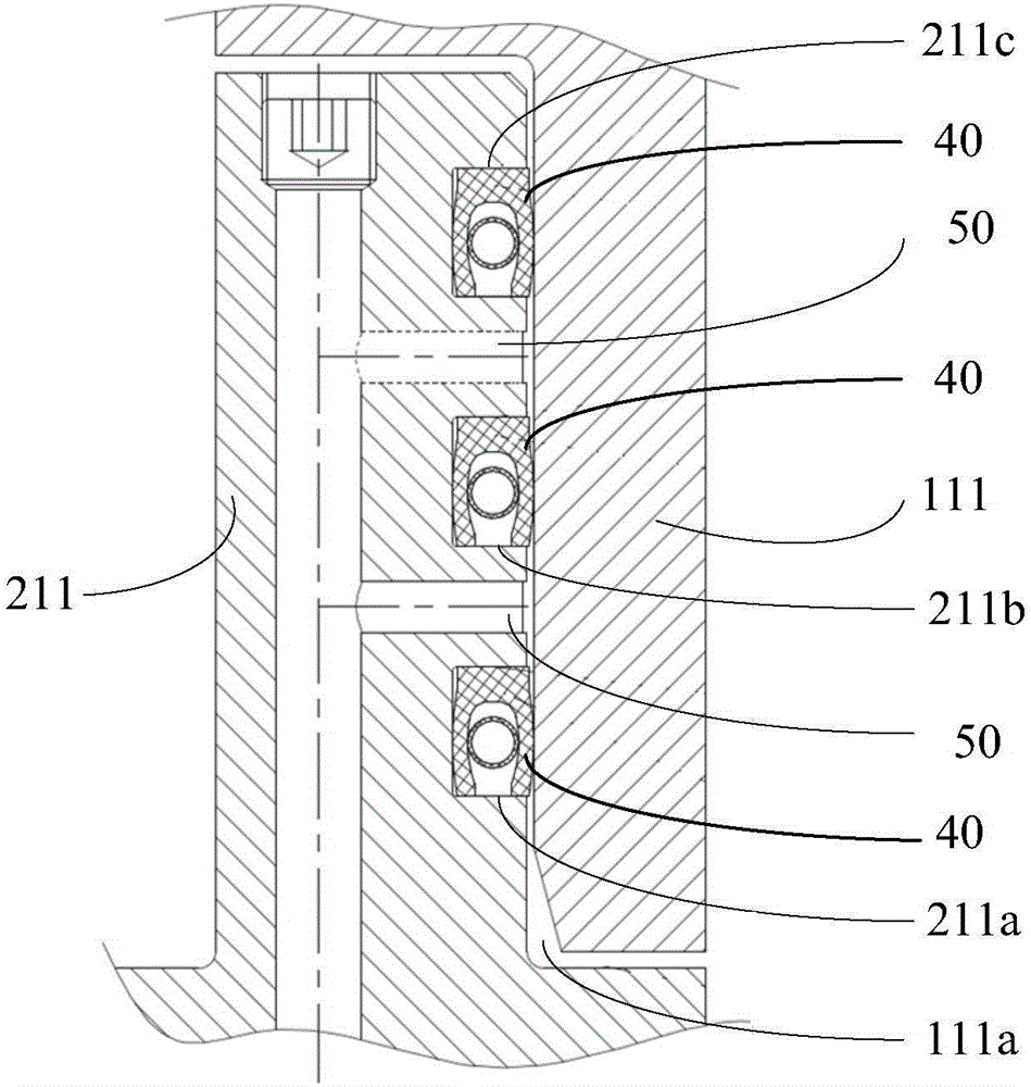
[0024] figure 1 is a structural schematic diagram of a rotary joint provided by an embodiment of the present invention, as shown in figure 1 As shown, the rotary joint includes a lower tubular body 20 and an upper tubular body 10 . figure 2 yes figure 1 The enlarged schematic diagram at A in the middle, such as figure 2 As shown, one end of the lower pipe body 20 is provided with a lower connecting flange 21, one end of the upper pipe body 10 is provided with an upper connecting flange 11, and the upper connecting flange 11 and the lower connecting flange 21 are rotatably butted through a slewing support 30. , the side of the lower connecting flange 21 opposite to the upper connecting flange 11 is provided with a first annular bos...


PUM


Abstract

The invention discloses a rotary joint for a single-point mooring system and belongs to the technical field of maritime work single-point mooring. The rotary joint comprises a lower tube body and an upper tube body, wherein a lower connecting flange is arranged on the lower tube body; an upper connecting flange is arranged on the upper tube body; a first annular boss is formed on the lower connecting flange; a second annular boss is formed on the upper connecting flange; as annular seal rings are arranged between the side wall of the first annular boss and the side wall of the second annular boss, the gap between the upper tube body and the lower tube body is sealed, and the seal rings cannot be greatly extruded when the rotary joint floats up and down; and leakage detection holes are formed between any two adjacent annular seal rings, leakage detection channels in one-to-one correspondence to the leakage detection holes are formed in the lower connecting flange, and the leakage detection holes communicate with the outside through the leakage detection channels, so that whether some seal rings fail to work or not can be judged according to whether crude oil flows out of the leakage detection channels, and accordingly, workers can be accurately informed of failures of the seal rings.

Description

technical field [0001] The invention relates to the technical field of marine single point mooring, in particular to a rotary joint of a single point mooring system. Background technique [0002] The single point mooring system is used as an offshore transfer terminal, which can be used for mooring and loading and unloading of crude oil by large ships. The single point mooring system usually consists of a buoy, a swivel joint arranged on the buoy and an underwater hose, and one end of the swivel joint is connected to the underwater hose. The buoy floats on the sea surface, and the tanker is connected to the other end of the swivel joint through the floating hose, so that the crude oil on the tanker can be sent to the submarine pipeline through the underwater hose, and then transported to the crude oil storage tank on the shore. [0003] The swivel joint mainly includes an upper pipe body and a lower pipe body, the upper pipe body and the lower pipe body are docked and can r...

Claims


Application Information

Patent Timeline
Patent Type & Authority Applications(China)
IPC IPC(8): F16L27/08F17D5/02
CPCF16L27/08F17D5/02
Inventor 熊大柱周英辉赵雷刚田永珍王建国
Owner WUHAN MARINE MACHINERY PLANT
Learn More