Eureka AIR delivers breakthrough ideas for toughest innovation challenges, trusted by R&D personnel around the world.

Door body for refrigeration and freezing device and refrigeration and freezing device

A technology for refrigerating and freezing devices and doors, which is applied to household refrigeration devices, cooling fluid circulation devices, applications, etc., can solve the problems of easily damaged display control components, increased thickness of the door, and reduced quality of the door, avoiding cold and heat. The effect of boundary phenomenon, prolonging service life and improving quality

Active Publication Date: 2017-05-10
HAIER SMART HOME CO LTD
View PDF7 Cites 4 Cited by
  • Summary
  • Abstract
  • Description
  • Claims
  • Application Information

AI Technical Summary

Problems solved by technology

At the same time, the accommodating cavity is a relatively closed space, and a large amount of heat generated by the display control components during operation cannot be effectively dissipated. As a result, there will be a junction between cold and heat in the accommodating cavity, resulting in condensation of the display control components. Furthermore, the display control components are easily damaged, seriously reducing the quality of the entire door body
[0003] In order to solve the problem of condensation, in the prior art, two methods are usually adopted: increasing the thickness of the foam layer or increasing the assembly gap between the display control component and the door body. However, this not only cannot dissipate the heat generated by the display control component well, It will also increase the thickness of the entire door body

Method used


Image

  • Door body for refrigeration and freezing device and refrigeration and freezing device
  • Door body for refrigeration and freezing device and refrigeration and freezing device
  • Door body for refrigeration and freezing device and refrigeration and freezing device

Examples


Embodiment Construction

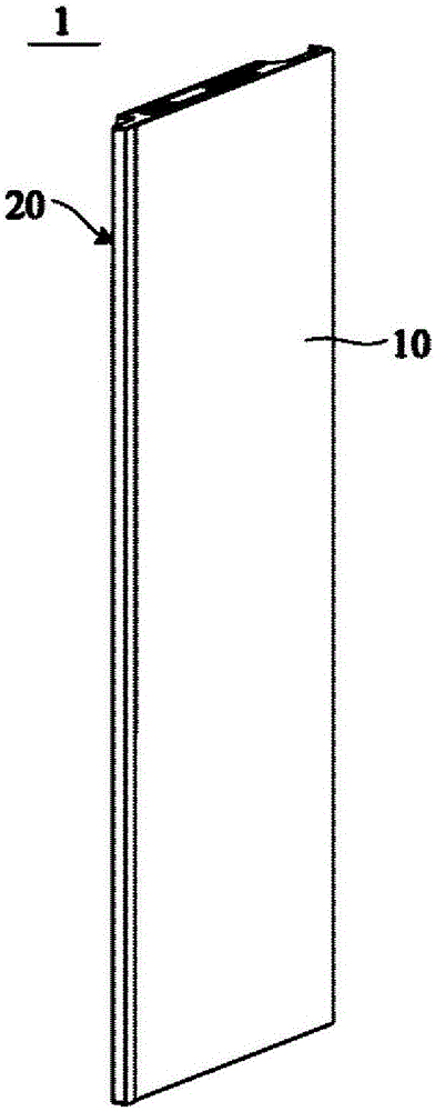
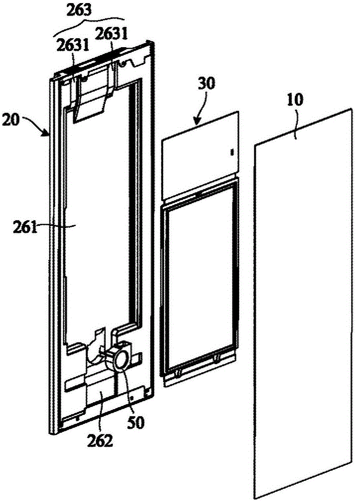
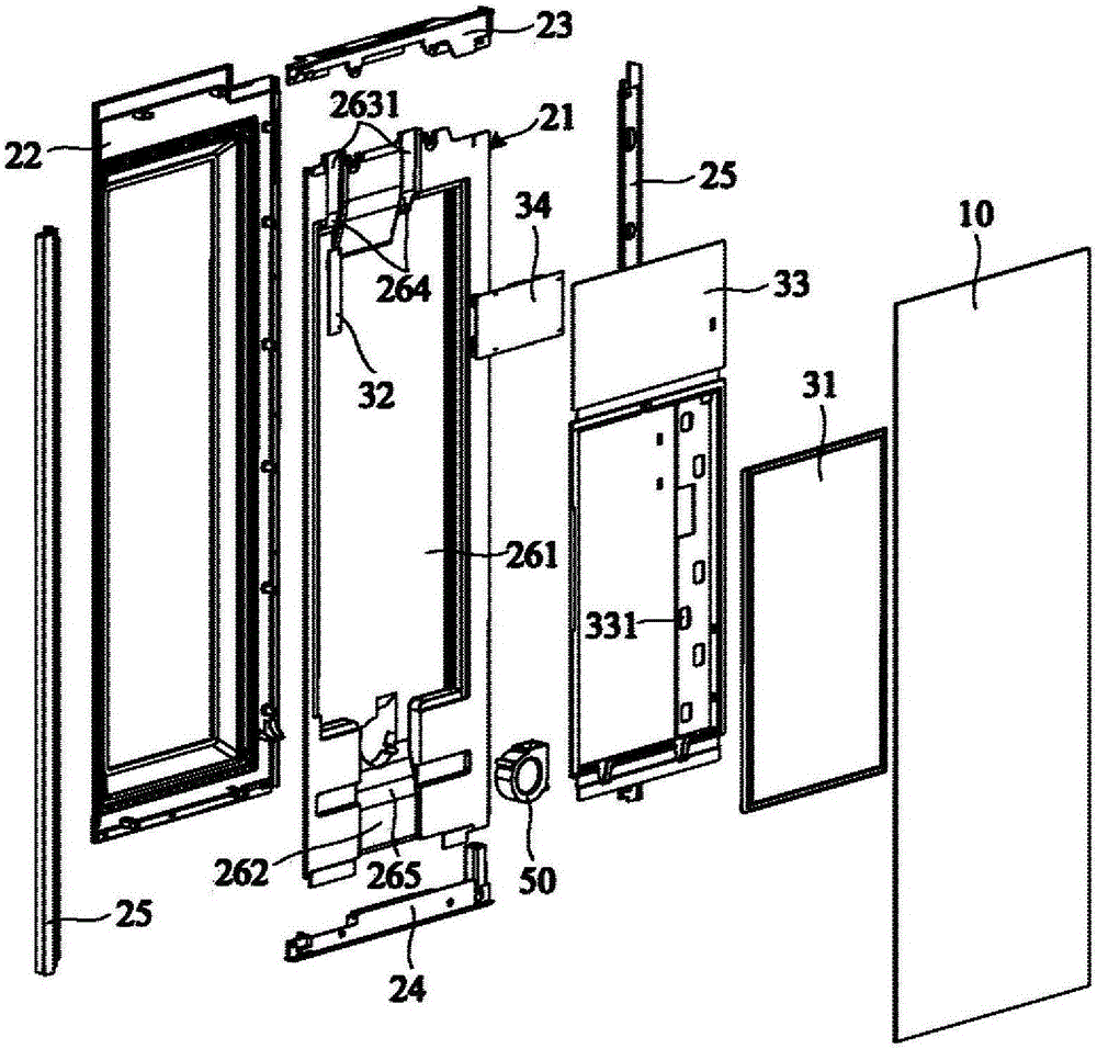
[0040] Embodiments of the present invention firstly provide a door body for a refrigerating and freezing device, figure 1 is a schematic structural diagram of a door body for a refrigerating and freezing device according to an embodiment of the present invention, figure 2 It is a schematic exploded view of a partial structure of a door body for a refrigerating and freezing device according to an embodiment of the present invention. see Figure 1 to Figure 2 , the door body 1 for refrigerating and freezing devices according to the embodiment of the present invention includes a panel 10 for forming the front part of the door body 1, a display control assembly 30 for providing a display touch function, and a panel 10 for forming the rear part of the door body 1. Door body foam assembly 20. The display control component 30 is disposed between the door body foam component 20 and the panel 10 , that is, the display control component 30 is disposed at the front side of the door bo...


PUM


Abstract

The invention relates to a door body for a refrigeration and freezing device and the refrigeration and freezing device. The door body comprises a panel used for forming the front portion of the door body, a display control component used for providing the display touch control function and a door body foaming component used for forming the rear portion of the door body. The display control component is arranged between the door body foaming component and the panel. The front surface of the door body foaming component forms a recess which is recessed backwards and vertically through, and vertically-through heat dissipation air ducts are defined between the door body foaming component and the display control component and between the door body foaming component and the panel. By the adoption of the door body, heat dissipation can be conducted effectively, it is avoided that condensation is generated on the display control component, the quality of the display control component is improved, and the service life of the display control component is prolonged. The refrigeration and freezing device comprises a box body and the door body, storage spaces used for storing objects are defined in the box body, and the door body is directly or indirectly connected to the box body and used for opening or closing at least part of the storage spaces.

Description

technical field [0001] The invention relates to refrigeration and freezing technology, in particular to a door body for a refrigeration and freezing device and the refrigeration and freezing device. Background technique [0002] In order to meet people's needs, some existing refrigerators are provided with display control components with a touch display function. In order to facilitate the user's operation, the display control components are generally arranged on the door body of the refrigerator. The door body of the refrigerator is generally a thin-plate-shaped member, and there must be an accommodation cavity for installing the display control component in it. Therefore, the thickness of the foam layer of the door body opposite to the accommodation cavity is relatively thin, and part of the refrigerator storage space is cold. The amount is easy to leak into the accommodation cavity through the thinner foam layer. At the same time, the accommodating cavity is a relativel...

Claims


Application Information

Patent Timeline
IPC IPC(8): F25D23/02F25D21/04F25D29/00
CPCF25D21/04F25D23/02F25D23/028F25D29/003F25D2323/02F25D2400/36
Inventor 朱云涛邹磊齐钢军刘庆林马海军董钦
Owner HAIER SMART HOME CO LTD
Why Eureka
Eureka Blog
Learn More