
Integrated electrode slapper exploder

A technology integrating electrodes and impact plates, applied in the field of pyrotechnics, can solve problems such as the influence of the reliability of the detonator, and achieve the effect of remarkable effect, better electrical conductivity, and reduction of welding points.

Inactive Publication Date: 2017-05-10
INST OF CHEM MATERIAL CHINA ACADEMY OF ENG PHYSICS
View PDF5 Cites 2 Cited by
  • Summary
  • Abstract
  • Description
  • Claims
  • Application Information

AI Technical Summary

Problems solved by technology

However, the shock plate assembly needs additional welding electrodes to connect with the detonation system, and the quality and strength of the solder joints will affect the reliability of the detonator

Method used


Image

  • Integrated electrode slapper exploder
  • Integrated electrode slapper exploder

Examples


Embodiment 1

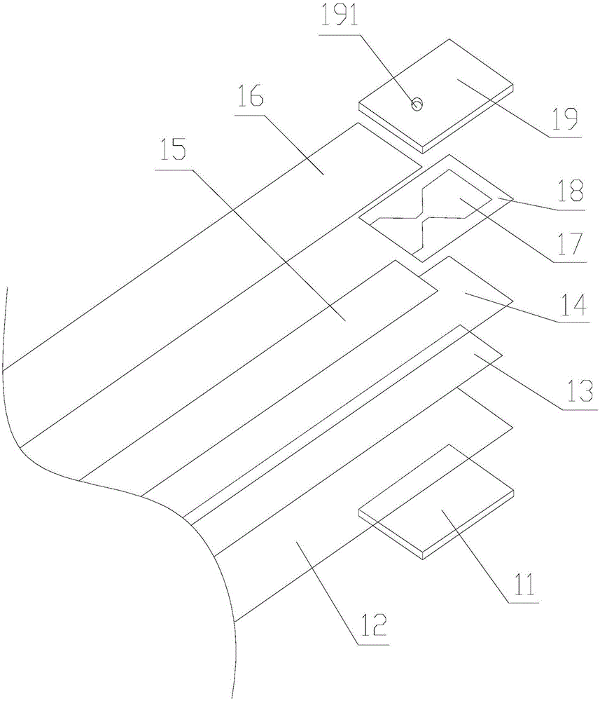
[0022] Such as figure 1 As shown, an integrated electrode impact sheet detonator includes a reflective sheet A11, an integrated electrode assembly, an explosive foil A17, a flyer layer A18 and an accelerating chamber A19. The upper surface of the integrated electrode assembly is provided with an explosive foil A17. Flyer layer A18 is stacked on top of foil A17, reflector A11 is fitted on the lower surface of the end of the integrated electrode assembly, and acceleration bore A19 is also provided on the upper surface of the end of the integrated electrode assembly, which is tightly clamped between the acceleration bore A19 and the reflector A11 Hold the end of the integrated electrode assembly, the flyer layer A18 and the explosive foil A17 are overlapped up and down between the lower surface of the acceleration chamber A19 and the upper surface of the end of the integrated electrode assembly. The acceleration chamber A19 corresponds to the center of the explosion foil A17 with an...

Embodiment 2

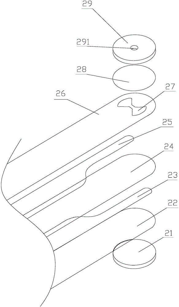
[0027] Such as figure 2 As shown, an integrated electrode impact sheet detonator includes a reflective sheet B21, an integrated electrode assembly, an explosive foil B27, a flyer layer B28 and an accelerating chamber B29. The upper surface of the integrated electrode assembly is provided with an explosive foil B27. Flyer layer B28 is stacked on top of foil B27, reflector B21 is fitted on the lower surface of the end of the integrated electrode assembly, and acceleration bore B29 is also provided on the upper surface of the end of integrated electrode assembly, which is tightly clamped between the acceleration bore B29 and reflector B21 Hold the end of the integrated electrode assembly, the flyer layer B28 and the explosive foil B27 are overlapped up and down between the lower surface of the accelerating chamber B29 and the upper surface of the end of the integrated electrode assembly. The accelerating chamber B29 corresponds to the center of the explosive foil B27 with an accel...


PUM

PropertyMeasurementUnit
Thicknessaaaaaaaaaa
Thicknessaaaaaaaaaa

Abstract

The invention discloses an integrated electrode slapper exploder. The integrated electrode slapper exploder comprises an integrated electrode assembly and an acceleration bore. A reflector plate is arranged on the lower surface of the end of the integrated electrode assembly in a matched mode. The acceleration bore is arranged on the upper surface of the end of the integrated electrode assembly. The end of the integrated electrode assembly is tightly clamped between the acceleration bore and the reflector plate. A slapper layer and explosion foil are stacked up and down to be located between the acceleration bore and the end of the integrated electrode assembly. An acceleration bore hole is formed in the position, corresponding to the center of the explosion foil, of the acceleration bore. The integrated electrode assembly is formed by sequentially pressing a lower insulating layer, a lower electrode core layer, a middle insulating layer, an upper electrode core layer, an upper insulating layer, the explosion foil and the slapper layer. The lower electrode core layer is in circuit connection with one end of the explosion foil, and the upper electrode core layer is in circuit connection with the other end of the explosion foil. According to the integrated electrode slapper exploder, the upper electrode core layer, the explosion foil and the lower electrode core layer form a circuit loop. After the explosion foil is powered up, electrical explosion can generate plasma to impact the slapper layer, the slapper layer is made to fly out of the acceleration bore hole of the acceleration bore, and percussion charging is performed to achieve the detonation function of slappers.

Description

Technical field [0001] The present invention relates to the technical field of pyrotechnics, and in particular to an impulse piece detonator with integrated electrodes. Background technique [0002] Shock disc detonator is a kind of high-energy pyrotechnic device that is only sensitive to short pulses. It was first proposed by JRStroud of Lawrence Livermore Laboratory at the annual meeting of the Fuse Department of the Ammunition Technology Department of the American War Readiness Association. Its safety and excellent reliability have received extensive attention from research institutions and the military, which has allowed it to develop rapidly and be widely used in inline fuzes. Due to the needs of the battlefield environment, the fuze system has always been miniaturized and integrated as the development direction, especially with the development of MEMS technology, the integration of the fuze system is getting higher and higher, and the integration of the corresponding impact...

Claims


Application Information

Patent Timeline
IPC IPC(8): F42C19/08
CPCF42C19/08
Inventor 孙秀娟付秋菠王窈杨爽郭菲
Owner INST OF CHEM MATERIAL CHINA ACADEMY OF ENG PHYSICS
Learn More