Bearing fault detection method and system for gear box
A fault detection and gearbox technology, which is applied in the testing of mechanical bearings, measuring devices, and mechanical components, etc., can solve the problem that the detection results of a single workpiece cannot be accurately recorded, the original data of manual testing cannot be saved, and the accuracy depends on and other problems to achieve the effect of reducing major economic losses, reducing low-frequency interference, and improving accuracy
- Summary
- Abstract
- Description
- Claims
- Application Information
AI Technical Summary
Problems solved by technology
Method used
Image
Examples
Embodiment 1
[0054] A specific embodiment of the method of the present invention is: a gearbox bearing fault detection method, comprising the following steps:
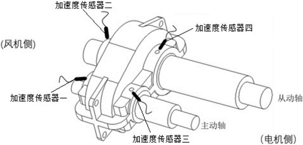
[0055] S1. Set the decibel thresholds of four positions of different types of bearings in the bearing run-in test in the fault judgment module, and establish a defect database; the four positions are respectively the reserved holes near the drive shaft on the fan side of the gearbox, and the fan side At the reserved hole near the driven shaft, at the reserved hole near the driving shaft on the motor side, and at the reserved hole near the driven shaft on the motor side, the decibel thresholds of the four positions are respectively the decibel threshold of the driving shaft on the fan side and the driven shaft on the fan side. Decibel threshold, decibel threshold of the motor-side driving shaft and decibel threshold of the motor-side driven shaft;
[0056] S2. In the bearing run-in test, the vibration acceleration value of the drivi...
specific Embodiment approach
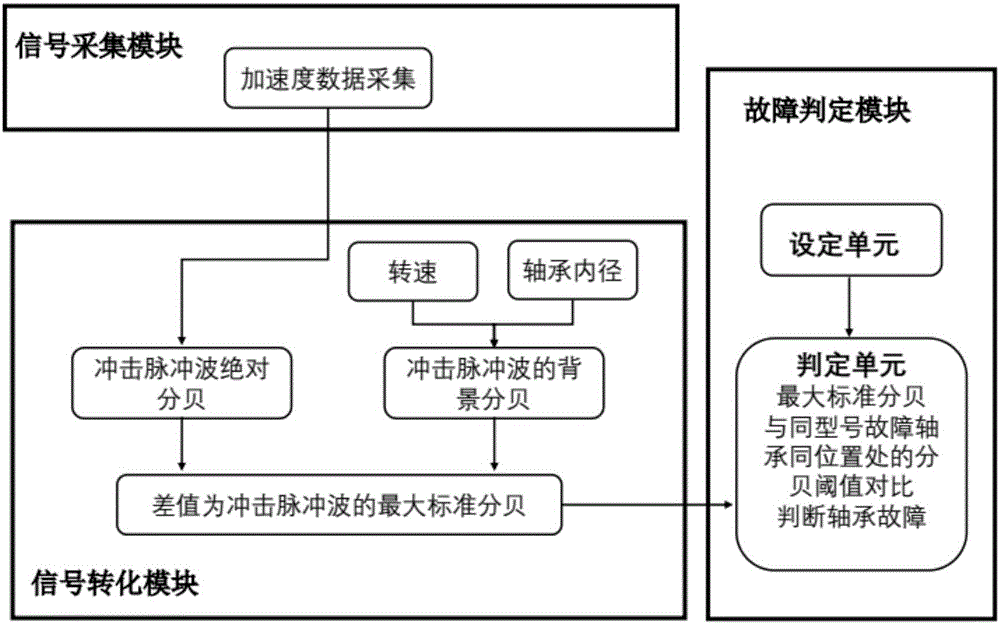
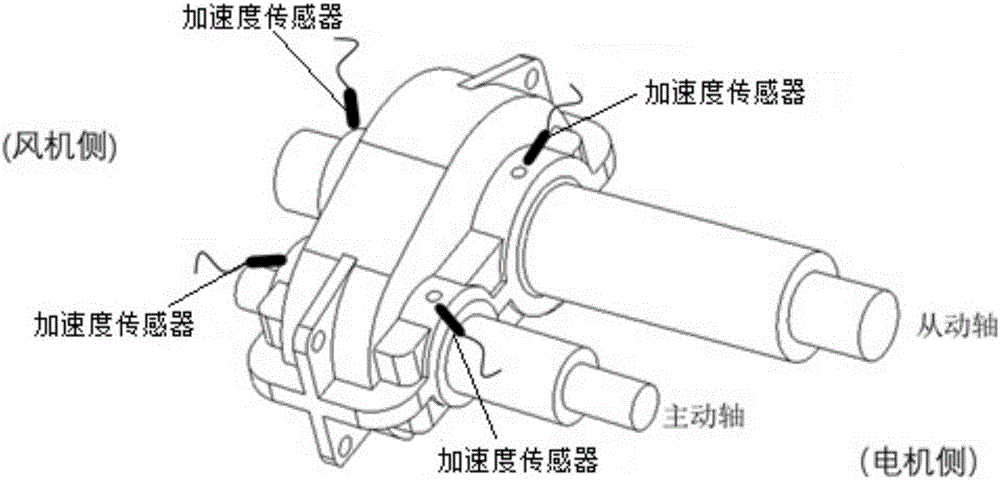
[0069] figure 2 As shown, a specific implementation of the system of the present invention is: a gearbox bearing fault detection system, including a signal acquisition module, the signal acquisition module includes shock pulse wave acceleration data used to detect the vibration of the test bearing during the running-in process The acceleration sensor is characterized in that: the acceleration sensor is respectively arranged at the reserved hole near the driving shaft of the fan side of the bearing gearbox, the reserved hole near the driven shaft of the fan side, the reserved hole near the driving shaft of the motor side and the motor At the reserved hole near the side driven shaft, image 3 The schematic diagram of the layout of each acceleration sensor is shown; the shock pulse wave acceleration data of the vibration at the four positions of the test bearing are respectively the vibration acceleration value of the driving shaft on the fan side, the vibration acceleration val...
PUM
 Abstract
Description
Claims
Application Information
 - R&D
- Intellectual Property
- Life Sciences
- Materials
- Tech Scout
- Unparalleled Data Quality
- Higher Quality Content
- 60% Fewer Hallucinations
Browse by: Latest US Patents, China's latest patents, Technical Efficacy Thesaurus, Application Domain, Technology Topic, Popular Technical Reports.
© 2025 PatSnap. All rights reserved.Legal|Privacy policy|Modern Slavery Act Transparency Statement|Sitemap|About US| Contact US: help@patsnap.com


