
Method for detecting micro defect inside metal material

A technology of metal materials and detection methods, which is applied in the direction of analyzing materials, using stable tension/pressure to test the strength of materials, measuring devices, etc., can solve the problems of time-consuming and cost, and improve the efficiency, accuracy and reliability of flaw detection , high detection range and high precision

Inactive Publication Date: 2017-05-10
武汉钢铁有限公司
View PDF5 Cites 8 Cited by
  • Summary
  • Abstract
  • Description
  • Claims
  • Application Information

AI Technical Summary

Problems solved by technology

Ultrasonic fatigue test technology is an accelerated fatigue test method, and its vibration frequency is as high as 2.0×10 4 Hz, the fatigue test can be completed quickly, for example: complete a 10 7 For the fatigue test, the 40Hz hydraulic servo fatigue testing machine needs to work continuously for 69.5 hours, which consumes a lot of time and cost, while the ultrasonic fatigue testing technology only takes about 20 minutes

Method used


Image

  • Method for detecting micro defect inside metal material
  • Method for detecting micro defect inside metal material
  • Method for detecting micro defect inside metal material

Examples


Embodiment 1

[0043] Taking a welded steel as an example, the flaw detection is carried out at the weld.

[0044] 1) Measure the elastic modulus of welded steel E=206GPa, density ρ=7850kg / m 3 .

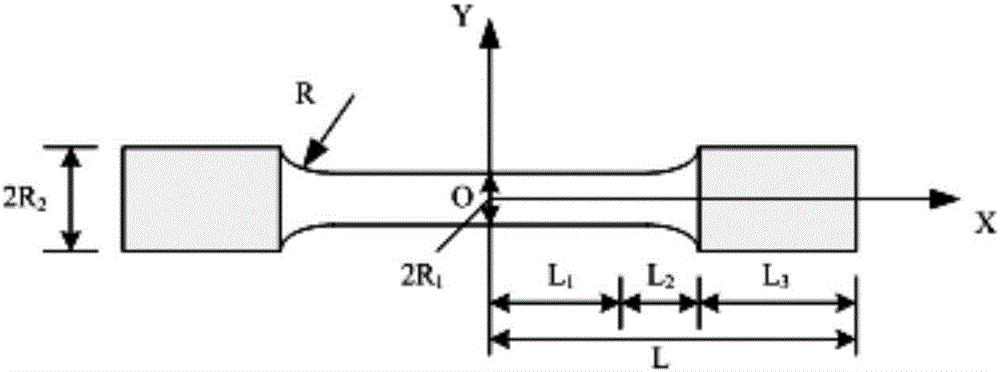
[0045] 2) Design the size of the arc-shaped ultrasonic fatigue specimen with equal cross-section for flaw detection. Pre-determined size parameters: half of the total length of the variable section of the sample L 1 =15mm, the length L of the variable section section of the sample 2 =5mm, the radius R of the equal section of the sample 1 = 2mm, the radius R at both ends of the sample 2 = 5mm. The length L at both ends of the sample can be calculated from the calculation formula (1) 3 =12.16mm.

[0046] 3) According to the designed size parameter L 1 , L 2 , L 3 , R 1 , R 2 The welded steel blank is processed into an arc-shaped ultrasonic fatigue specimen with a constant cross-section, so that the weld is located in the middle of the specimen.

[0047] 4) Polish and polish the equal sec...

Embodiment 2

[0051] Taking a high-strength automobile spring steel as an example, carry out flaw detection on it.

[0052] 1) Measure the spring steel elastic modulus E = 206GPa, density ρ = 7850kg / m 3 .

[0053] 2) Design the size of the arc-shaped ultrasonic fatigue specimen with equal cross-section for flaw detection. Pre-determined size parameters: half of the total length of the variable section of the sample L 1 =18mm, the length L of the variable section section of the sample 2 =5mm, the radius R of the equal section of the sample 1 = 2mm, the radius R at both ends of the sample 2 = 5mm. The length L at both ends of the sample can be calculated according to the calculation formula (1) 3 = 10.02 mm.

[0054] 3) According to the designed size parameter L 1 , L 2 , L 3 , R 1 , R 2 The spring steel billet is processed into an arc-shaped ultrasonic fatigue specimen with a constant cross-section.

[0055] 4) Shot blasting is carried out on the equal section section of the pro...


PUM

PropertyMeasurementUnit
depthaaaaaaaaaa
diameteraaaaaaaaaa
densityaaaaaaaaaa

Abstract

The invention discloses a method for detecting a micro defect inside a metal material. The method comprises the following steps: (1) designing a variable-section ultrasonic fatigue test sample having a circular cross section and containing a constant-section segment according to an elastic modulus and a density value of a metal material to be detected, wherein the size of the test sample is designed according to a following formula: (as shown in the specification); (2) installing the test sample on an ultrasonic fatigue test machine to perform a fatigue test until the test sample is broken; and (3) observing a fracture of the broken test sample, measuring a defect size on the fracture of the test sample, that is a maximum defect size of the metal material. The method can rapidly, intuitively and quantitatively determine the defect in the metal material and can determine the micro defects which are 0.1 mm or smaller and even 10 micrometers or smaller inside the metal material.

Description

technical field [0001] The invention relates to a metal material quality inspection technology, in particular to a method for detecting tiny defects inside a metal material. Background technique [0002] If the size of the internal defects introduced by the metal material in the smelting process is too large, its fatigue performance will be greatly reduced, which will also seriously shorten its service life, and even cause serious safety accidents due to premature failure of the material. Therefore, for metal materials, such as 3D printed metal materials or welded structures, flaw detection after leaving the factory is of great significance to ensure the safe application of materials. Traditional metal material flaw detection methods include X-ray flaw detection method and ultrasonic flaw detection method, and these methods have their own shortcomings. Among them, the x-ray flaw detection method is sensitive to volume defects, but it is difficult to find linear defects, esp...

Claims


Application Information

Patent Timeline
Patent Type & Authority Applications(China)
IPC IPC(8): G01N3/08G01N1/28G01N1/32
CPCG01N3/08G01N1/286G01N1/32G01N2001/2866G01N2203/0067G01N2203/0073G01N2203/0268G01N2203/0298
Inventor 彭文杰薛欢刘冬孔君华吴立新彭润平
Owner 武汉钢铁有限公司
Learn More