
Method for designing loop-optimization-based emission beam matrix in FDA-MIMO radar

A technology of transmitting beam and loop optimization, applied in the field of radar communication, which can solve problems such as high signal processing complexity

Active Publication Date: 2017-05-10
HUBEI UNIV OF TECH
View PDF3 Cites 30 Cited by
  • Summary
  • Abstract
  • Description
  • Claims
  • Application Information

AI Technical Summary

Problems solved by technology

[0004] However, in the above frequency-steered-array MIMO radar system, obtaining high-resolution estimation requires more transmitted waveforms and snapshots, resulting in higher signal processing complexity

Method used


Image

  • Method for designing loop-optimization-based emission beam matrix in FDA-MIMO radar
  • Method for designing loop-optimization-based emission beam matrix in FDA-MIMO radar
  • Method for designing loop-optimization-based emission beam matrix in FDA-MIMO radar

Examples


Embodiment Construction

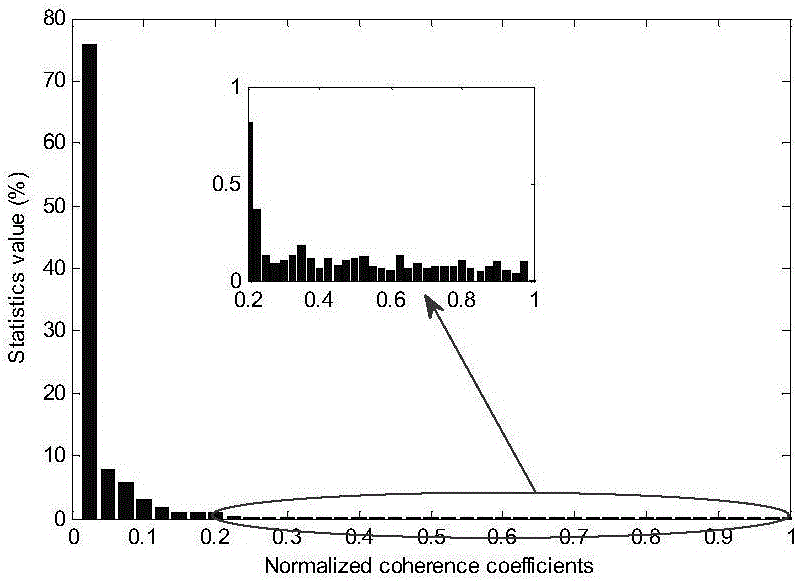
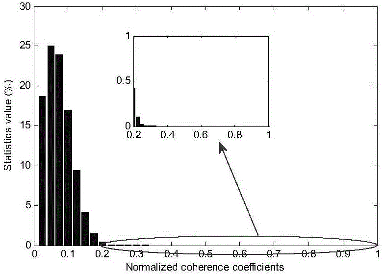
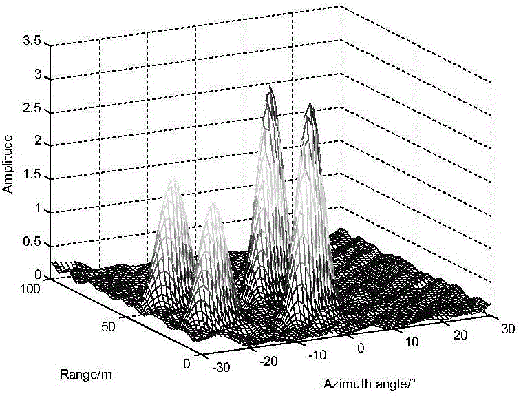
[0030] The invention provides a transmit beam matrix design method based on cycle optimization in FDA-MIMO radar. The frequency-steered array can generate angle- and distance-dependent transmit beams by adding a small frequency increment to adjacent array elements, which provides the possibility for the joint positioning of the target's angle and distance parameters. The invention utilizes this characteristic, combines the frequency control array and the MIMO radar, and realizes the joint estimation of the distance and angle of multiple targets by optimizing the design of the transmitting beam matrix. include:

[0031] Step 1. According to the actual needs and the characteristics of the frequency control array MIMO radar system, determine the transmitting carrier, frequency increment, and the number of transmitting and receiving antennas, and establish the frequency control array MIMO radar system model;

[0032] Step 2, use the cyclic optimization method to design the transm...


PUM


Abstract

The invention provides a method for designing a loop-optimization-based emission beam matrix in a FDA-MIMO radar. The method is characterized in that the feature that when a small frequency increment is added to a frequency control matrix through adjacent matrix elements, emission beams with angles and distance dependence can be produced, and possibility is provided for the angle and distance parameter combined positioning of a target is utilized to combine with the frequency control matrix and an MIMO radar, and combined estimation of the distances and angles of multiple targets is achieved by optimally designing the emission beam matrix. The method specifically includes: determining emission carrier waves, the frequency increment and emission receiving antenna number according to actual needs and the features of a frequency control matrix MIMO radar system, and building a frequency control matrix MIMO radar system model; using a loop optimization method to design the emission beam matrix of the radar; verifying the performance of estimated distances, angles and amplitudes on the basis of the emission beam matrix. The method is essentially a method minimizing the mutual coherence principle of a perception matrix in a thinning model to increase distance and angle-dimension resolution.

Description

technical field [0001] The invention belongs to the technical field of radar communication, and relates to a waveform design method in a multi-input multi-output radar of a new system, in particular to a design method of a transmit beam matrix based on cycle optimization in an FDA-MIMO radar. Background technique [0002] There is a small frequency increment between adjacent array elements in a frequency diverse array (FDA), which makes the beam scanning angle of the frequency diverse array beamformer change with distance. The angle and distance dependence of the frequency steered array radar beam provides the possibility for the joint positioning of the target's range and angle parameters. Although the transmitting beam of the frequency steerable array is related to the azimuth and distance of the target, its energy radiation has a unique "S" shape, which makes the beamforming of the frequency steerable array have coupling problems in the direction of distance and azimuth. ...

Claims


Application Information

Patent Timeline
Patent Type & Authority Applications(China)
IPC IPC(8): G01S7/282
CPCG01S7/282
Inventor 巩朋成涂斯纯李风从李婕张正文黄翔包泽胜刘陈
Owner HUBEI UNIV OF TECH
Learn More