Sealing structure for redox flow battery

A technology of sealed structure and liquid flow battery, which is applied in the direction of fuel cells, regenerative fuel cells, circuits, etc., can solve the problems of large bending and shear stress of bipolar plates, the inapplicability of nitrile rubber, and the impact on the performance of battery stacks, etc., to achieve Improved safety, low cost, and feasible process

Inactive Publication Date: 2017-05-10
SUZHOU JIURUN ENERGY TECH
View PDF5 Cites 5 Cited by
  • Summary
  • Abstract
  • Description
  • Claims
  • Application Information

AI Technical Summary

Problems solved by technology

[0003] The upper and lower protrusions in the U-shaped groove of the sealing ring are staggered from each other, and the outer plane of the U-shaped groove is sealed, which requires a large pre-tightening force
However, bipolar plates are usually made of brittle carbon materials, and the above fastening pressure is likely to cause large bending and shear stresses on the edges of the bipolar plates.
When the pressure is too high, the bipolar plate will be twisted or even damaged, which will affect the sealing performance and even directly lead to the scrapping of the entire battery stack
[0004] And because there is no positioning structure, the sealing ring is easy to deviate from its position after being placed in the groove of the plate frame. After the sealing ring is misplaced, there will be a risk of electrolyte leakage: First, the electrode material may be sandwiched between the sealing ring and the plate frame , leading to electrolyte leakage; second, there is a gap between the sealing ring and the electrode, and part of the electrolyte does not pass through the electrode, which will cause electrolyte leakage and affect the performance of the battery stack
In addition, the nitrile rubber used is not suitable for working in a long-term acid environment, especially in a high-temperature, medium-strong acid environment

Method used


Image

  • Sealing structure for redox flow battery
  • Sealing structure for redox flow battery
  • Sealing structure for redox flow battery

Examples


Embodiment 1

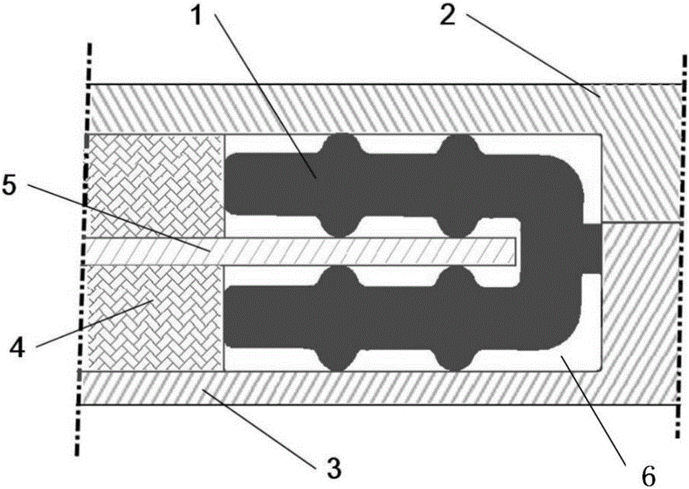
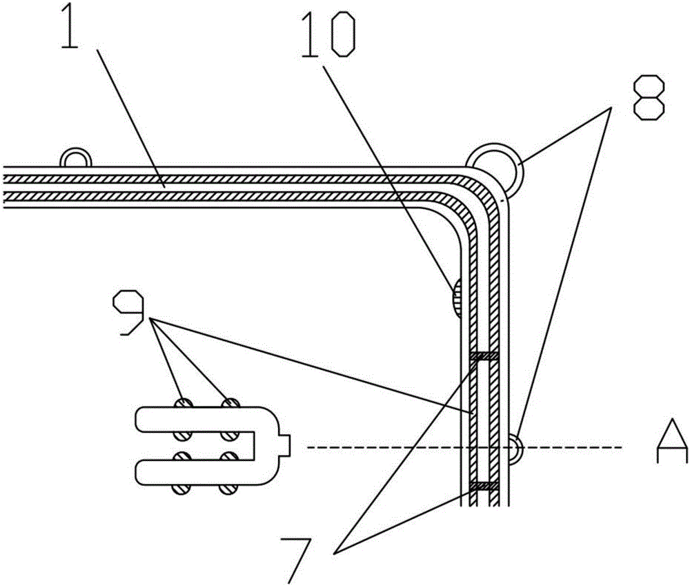
[0032] Example as Figure 1-3As shown, the material of sealing ring 1 in this embodiment is EPDM rubber, and its hardness is 60-75 degrees Shore; Greater than the depth of the groove 6 on the plate frame, the internal length and width of the sealing ring 1 are slightly smaller than that of the bipolar plate 5 . Such as figure 1 As shown in or 3, the cross section of the sealing ring 1 is a "匚"-shaped opening structure, the inner side of the opening is used to envelop the double-plate pole 5, and the upper and lower inner sides and two outer sides of the opening are provided with a total of 4 surfaces. 8 (4 rows and 2 rows) protruding long waterlines 9, the positions of two rows of long waterlines 9 are up and down. Between the two long waterlines 9 on the upper and lower outer surfaces of the sealing ring 1, several auxiliary waterlines 7 in the vertical direction are arranged to prevent the liquid inside the sealing ring 1 from leaking. The two inner sides of the "匚"-shap...

Embodiment 2

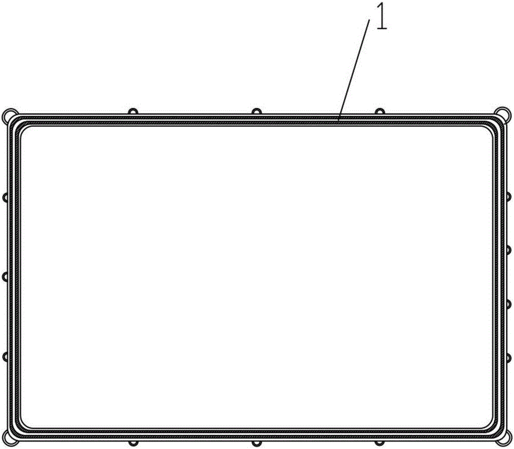
[0038] Example two such as Figure 4-5 As shown, the material of the sealing ring 1 in the second embodiment is fluorine rubber, and the hardness is 60-75 degrees Shore. The sealing ring 1 has a "□"-shaped structure, and the middle part of a short side of the sealing ring 1 is provided with a sealing structure tap 11 of a bipolar plate tap. The depth of the groove 6; the internal length and width of the sealing ring 1 is slightly smaller than the size of the bipolar plate 5; There are 8 (4 rows and 2 rows) protruding long waterlines 9 on the 4 surfaces of the upper and lower inner sides and the two outer sides, and the positions of the two rows of long waterlines 9 are up and down. Between the two long waterlines 9 on the upper and lower outer surfaces of the sealing ring 1, several auxiliary waterlines 7 in the vertical direction are arranged. The arrangement of the auxiliary waterlines 7 can prevent the liquid inside the sealing ring 1 from leaking. The long waterlines 9 o...


PUM

PropertyMeasurementUnit
hardnessaaaaaaaaaa

Abstract

The invention discloses a sealing structure for a redox flow battery. The sealing structure comprises a positive electrode plate frame and a negative electrode plate frame which are arranged adjacently; a groove is formed in the connecting place between the positive electrode plate frame and the negative electrode plate frame; a square-shaped sealing ring is embedded in the groove; the free thickness of the sealing ring is slightly greater than the depth of the groove; the cross section of the sealing ring adopts a rightward-n-shaped opening structure, and the inner side of the sealing ring is used for enveloping a dual-polar plate; at least two protruding long water lines are correspondingly arranged on the two inner side surfaces and two outer side surfaces of the rightward-n-shaped opening; and the distance between the two water lines which are correspondingly arranged on the upper and lower two inner side surfaces is slightly less than the thickness of the dual-polar plate. The sealing structure provided by the invention can effectively prevent the shortcomings of electrolyte leakage and electrolyte mixing in the existing redox flow battery; and in addition, the sealing structure has the advantages of simple structure, high sealing reliability, good-quality material, feasible process, convenience in installation, stable performance and the like.

Description

technical field [0001] The invention belongs to the technical field of liquid flow batteries, and in particular relates to a sealing structure for a liquid flow battery. Background technique [0002] At present, the sealing problem is the bottleneck restricting the service life of the flow battery. The stack of a flow battery consists of several battery cells. In the prior art CN 102867974 B, the sealing method between the positive and negative plate frame and the bipolar plate is as follows: Figure 6 , A battery cell includes a positive plate frame 16, a bipolar plate 15, electrodes, an ion isolation membrane, a negative plate frame 18, a sealing ring 17, and the like. The sealing ring is embedded in the groove between the plates and frames. The sealing ring is made of nitrile rubber with a hardness of 60 degrees, and the cross section adopts an inverted U-shaped groove structure. The upper and lower sides of the inverted U-shaped groove are respectively provided with pr...

Claims


Application Information

Patent Timeline
Patent Type & Authority Applications(China)
IPC IPC(8): H01M8/0271H01M8/0273H01M8/0276H01M8/18H01M8/2465H01M8/2485
CPCH01M8/0271H01M8/0273H01M8/0276H01M8/188H01M8/2465H01M8/2485Y02E60/50
Inventor 马志啟田清王聪康谭长永
Owner SUZHOU JIURUN ENERGY TECH
Why Eureka
Try Eureka