
Vibration self-generating indicator lamp

An indicator light, self-generating technology, applied in the direction of collectors, electric light sources, electromechanical devices, etc., can solve the problems of extremely high requirements on lighting lines, aging power supply lines, hidden dangers of fire safety, etc., to prevent environmental pollution, low production costs, The effect of avoiding safety hazards

Inactive Publication Date: 2017-05-10
罗瑞琪
View PDF6 Cites 6 Cited by
  • Summary
  • Abstract
  • Description
  • Claims
  • Application Information

AI Technical Summary

Problems solved by technology

[0003] Conventional lighting devices usually require power supply lines to provide electric energy, but in some areas on ships or vehicles, there are many restrictions on the layout of power supply lines, such as the cabin where the internal combustion engine power plant of the ship or vehicle is located, due to the fear of oil and gas volatilization and spark ignition Fires are caused, and the requirements for lighting lines are extremely high, and power supply lines are even completely prohibited in some areas; the usual operating environment of ships has adverse factors such as humidity, high temperature, and salt spray corrosion. There are lighting power supply lines that are prone to aging and bring fire safety hazards
However, in some areas of the ship, the cost of maintenance and replacement of lines is high and the specific construction is difficult

Method used


Image

  • Vibration self-generating indicator lamp
  • Vibration self-generating indicator lamp
  • Vibration self-generating indicator lamp

Examples


Embodiment 1

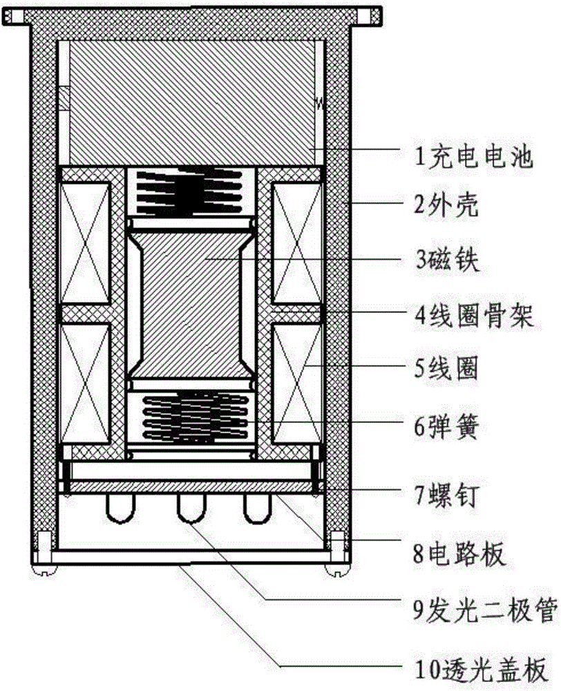
[0022] as attached figure 1 As shown, the coil bobbin 4 processed by insulating material (nylon rod or resin rod) is cylindrical, with a partition plate outside, and the coil 5 composed of a whole wire with an insulating layer is wound on the coil bobbin 4 , constitute the winding, the winding is divided into upper and lower parts by the partition plate on the coil frame 4, this is to reduce the difficulty of winding the coil 4 itself, and reduce the requirements of the insulation performance of the coil 5, the two ends of the coil are welded on the On the circuit board 8; the coil frame 4 is fixed in the middle of the shell of the cylindrical shell 2 to form a whole. The shell 2 is made of non-magnetic materials such as engineering plastics or synthetic resins.

[0023] The longitudinally stretchable spring 6 is placed in the middle cavity of the bobbin 4 , one end of which is fixed on the top and bottom of the bobbin 4 , and the other end is connected to the magnet 3 . The...


PUM


Abstract

The invention provides a vibration self-generating indicator lamp, which is a small, closed and independent self-generating lighting device. The specific structure is as follows: a housing is a cylindrical cavity shell with an opening in one end; the opening of the housing is covered with a fixed partition plate; a coil skeleton is a hollow cylinder; a groove for winding a coil is formed in the outer side wall of the hollow cylinder around the circumferential direction of the cylinder; a magnet is a steel and magnetized cylindrical permanent magnet; the coil skeleton is coaxially arranged in a cylindrical cavity of the housing and is located between the inner bottom surface of the housing and the fixed partition plate; the magnet is arranged at the hollow part of the coil skeleton; two ends of the magnet are fixedly connected with the inner bottom surface of the housing and the fixed partition plate through springs respectively; the coil is wound into the groove in the outer side wall of the coil skeleton; two ends of the coil are connected with a circuit board through wires; the circuit board completes the functions of rectification and electric energy storage; the stored electric energy is input into a rechargeable battery to drive a light-emitting diode to emit light; and the light-emitting diode is arranged outside the fixed partition plate.

Description

technical field [0001] The invention belongs to the technical field of self-power generation, and in particular relates to a vibration self-power generation indicator light. Background technique [0002] In some enclosed spaces inside ships or vehicles, because external natural light cannot be irradiated, and some parts or components require frequent maintenance, artificial light sources need to be provided for lighting; In darker conditions, auxiliary light sources are also required to indicate lighting; while in the bottom cabin, light source lighting is required to indicate the direction in the passage. For the above use environment or some other specific areas on the ship, weak lighting sources can meet the use requirements. [0003] Conventional lighting devices usually require power supply lines to provide electric energy, but in some areas on ships or vehicles, there are many restrictions on the layout of power supply lines, such as the cabin where the internal combu...

Claims


Application Information

Patent Timeline
IPC IPC(8): H02K35/02H02J7/32F21S9/02
CPCH02K35/02F21S9/02H02J7/32
Inventor 罗瑞琪
Owner 罗瑞琪
Learn More