Novel three-phase current converter topology based on modular multilevel converter

A modular multi-level, three-phase converter technology, applied in the direction of converting DC power input to DC power output, converting AC power input to DC power output, adjusting electrical variables, etc., can solve the problem of limiting the overall efficiency of the system, switching Loss and other issues, to achieve the effect of system volume and cost, reduce switching loss and conduction loss, and optimal design

Pending Publication Date: 2017-05-10
KUNMING UNIV OF SCI & TECH
View PDF7 Cites 6 Cited by
  • Summary
  • Abstract
  • Description
  • Claims
  • Application Information

AI Technical Summary

Problems solved by technology

In addition, the switching devices in the half-bridge sub-module will generate switching losses when switching, and at the same time, the swi

Method used


Image

  • Novel three-phase current converter topology based on modular multilevel converter
  • Novel three-phase current converter topology based on modular multilevel converter
  • Novel three-phase current converter topology based on modular multilevel converter

Examples


Example Embodiment

[0019] The present invention will be described in detail below in conjunction with the drawings and specific embodiments.

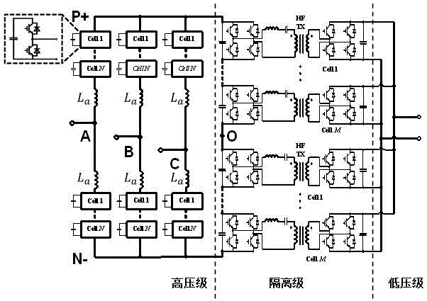
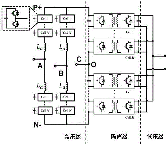
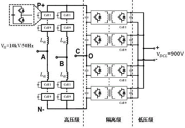
[0020] A new three-phase converter topology based on modular multilevel converters includes a high-voltage stage, an isolation stage, and a low-voltage stage. The high-voltage stage and the low-voltage stage are connected by an isolation stage. Bridge arm three-phase modular multilevel converter structure, two of the three phases are composed of upper bridge arm and lower bridge arm respectively. The upper bridge arm and lower bridge arm are composed of half-bridge sub-modules in series, and the third phase is composed of multiple Two capacitors are connected in series; the isolation stage adopts a high-frequency isolation mode, and is composed of a plurality of isolation sub-modules first in series and then in parallel.

[0021] The third-phase output terminal of the high-voltage stage is located at the midpoint of the capacitor series;

[0022] The sum of the...


PUM


Abstract

The invention relates to a novel three-phase current converter topology based on a modular multilevel converter, wherein the three-phase current converter belongs to the technical field of a power electronic converter. The three-phase current converter topology comprises a high-voltage electrode, an isolating electrode and a low-voltage electrode, wherein the high-voltage electrode has a three-phase structure. A four-bridge-arm three-phase modular multilevel converter structure is utilized, namely two phases in the three phases are composed of four bridge arms, and the output end of the three phase is obtained through serially connecting capacitors. The third phase output end of the high-voltage electrode is arranged at the middle point of the serially connected capacitors. The summation of voltages of all capacitors in the third phase is equal with a bus voltage. The isolating electrode is formed through serially connecting and then parallelly connecting a plurality of isolator modules in a high-frequency isolation manner. The number of sub-modules of the isolating electrode is determined according to the voltage of the isolating electrode and overvoltage resistance grade of an adopted switch device. The primary voltage grade of the sub-module of the isolating electrode can be different from the voltage grade of a semi-bridge sub-module of the high-voltage electrode. The novel three-phase current converter topology has advantages of small number of required sub-modules, low output voltage harmonic wave, high system efficiency, etc.

Description

technical field [0001] The invention belongs to the technical field of power electronic converters, and in particular relates to a modular three-phase converter topology used in power grids and the like. Background technique [0002] Modular Multilevel Converter (MMC) has gained more and more applications in the field of high-voltage and large-capacity because of its advantages of modularization, easy expansion, common DC bus, high efficiency, and small output voltage harmonics. Applications. The basic structure of an existing MMC-based three-phase converter is shown in Figure 1, in which the high-voltage stage is an MMC based on a half-bridge sub-module. The MMC is divided into two parts, the upper bridge arm and the lower bridge arm, and each bridge arm is composed of N Two half-bridge sub-modules are connected in series, and a snubber inductor is usually connected in series between the upper bridge arm and the lower bridge arm L a Prevent the bridge arm from passing t...

Claims


Application Information

Patent Timeline
IPC IPC(8): H02M7/219H02M3/335
CPCH02M3/33569H02M7/219H02M1/007
Inventor 鲁思兆李思奇
Owner KUNMING UNIV OF SCI & TECH
Why Eureka
Try Eureka