High frequency time-division multi-phase power converter

Inactive Publication Date: 2020-04-30
LIN JING YUAN
View PDF23 Cites 8 Cited by
  • Summary
  • Abstract
  • Description
  • Claims
  • Application Information

AI Technical Summary

Benefits of technology

[0008]The technical problem to be solved by the present invention is to provide a high frequency time-division multi-phase power converter, which c

Problems solved by technology

However, since the magnetic core of iron-material transformer commonly used in the existing switching power supply has the limitation in frequency, the increase of the frequency is limited.
Furthermore, the existing silicon-based semiconductor components have bigger parasitic conductance in h

Method used


Image

  • High frequency time-division multi-phase power converter
  • High frequency time-division multi-phase power converter
  • High frequency time-division multi-phase power converter

Examples


first embodiment

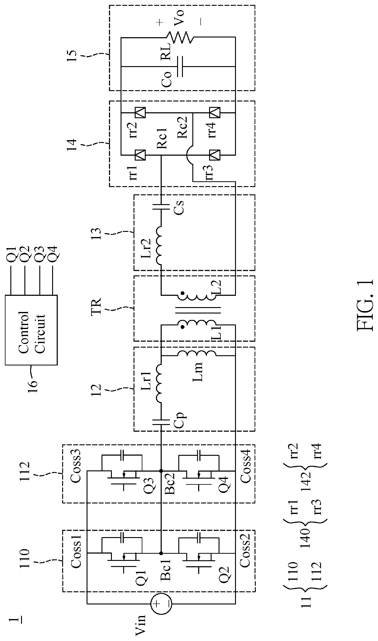
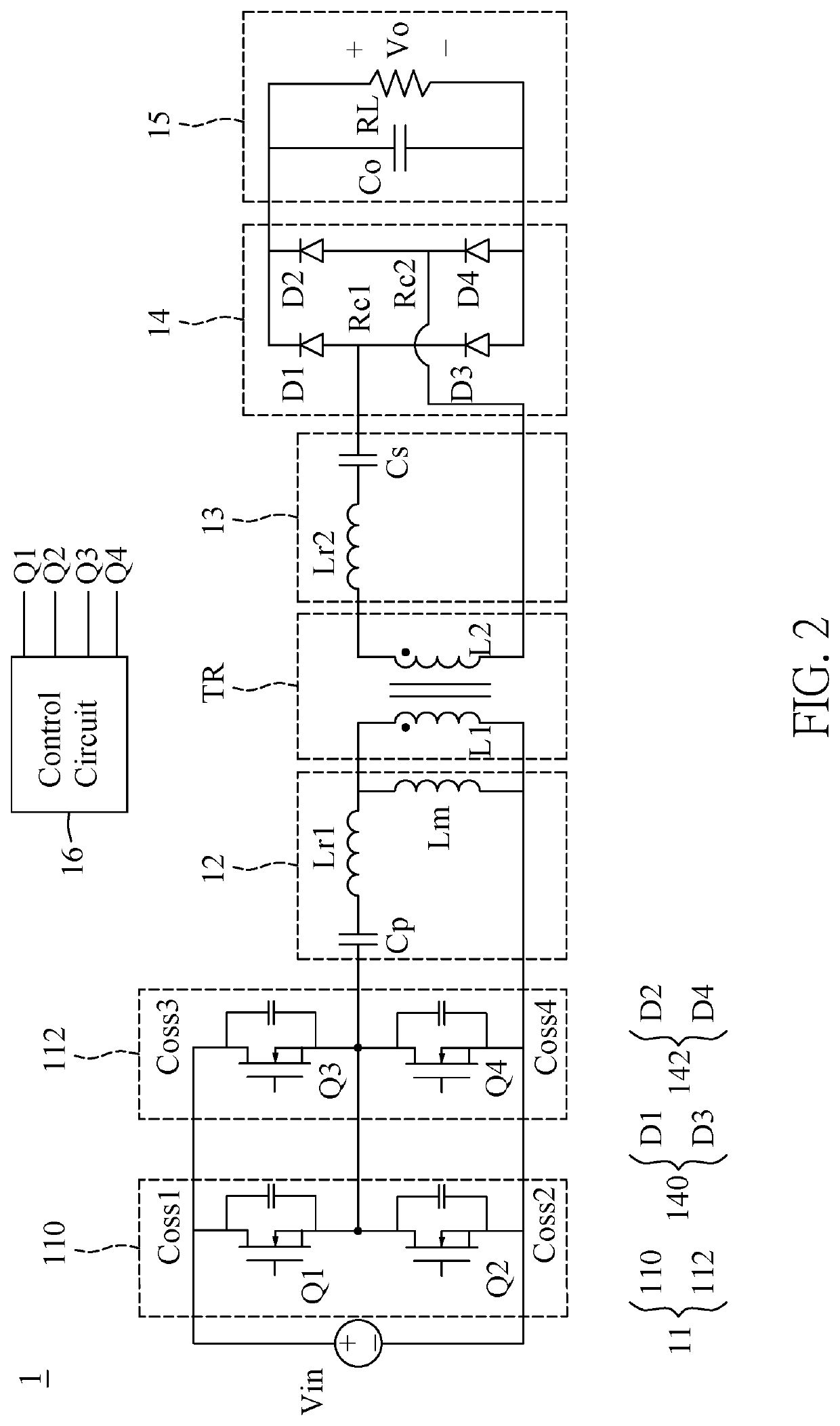
[0032]Referring to FIG. 1, a first embodiment of the present disclosure provides a high frequency time-sharing multiphase power converter 1, which includes a power source Vin, a switching circuit 11, a first resonant tank 12, coreless transformer TR, a second resonant tank 13, an output rectifier circuit 14, an output load circuit 15 and a control circuit 16.

[0033]The switching circuit 11 is coupled to the power source Vin and includes a first half bridge circuit 110 and a second half bridge circuit 112 connected in parallel. The first resonant tank 12 is coupled to the switching circuit 11 and includes a first resonant capacitor Cp, a first resonant inductor Lr, and a magnetizing inductor Lm. The coreless transformer TR is coupled to the first resonant tank 12 and includes a primary side coil L1 and a secondary side coil L2.

[0034]The second resonant tank 13 is coupled to the coreless transformer TR and includes a second resonant capacitor Cs and a second resonant inductor Lr2. The ...

second embodiment

[0055]Reference is now made to FIG. 6, which is a circuit layout of a high frequency time-division multi-phase power converter according to a second embodiment of the present disclosure. The second embodiment of the present disclosure provides a high frequency time-division multi-phase power converter 2, which includes the power source Vin, the switching circuit 21, the converter circuit 22, the output load circuit 25 and the control circuit 26.

[0056]The switching circuit 21 is coupled to the power source Vin and includes a plurality of first switches Q21, Q22, . . . , Q2N connected in parallel with respect to a first common end N21 and a second common end N22. The converter circuit 22 is coupled to the switch circuit 21 and includes a diode D and an inductor L, and the output load circuit 25 is coupled to the converter circuit 22 and includes an output capacitor Co and an output load RL.

[0057]In the present embodiment, the high frequency time-division multi-phase power converter 2 ...

third embodiment

[0061]Reference is now made to FIG. 8, which is a circuit layout of a high frequency time-division multi-phase power converter according to a third embodiment of the present disclosure. The third embodiment of the present disclosure provides the high frequency time-division multi-phase power converter 2, which includes the power source Vin, the switching circuit 21, the converter circuit 22, the output load circuit 25 and the control circuit 26.

[0062]The switching circuit 21 is coupled to the power source Vin and includes a plurality of first switches Q21, Q22, . . . , Q2N connected in parallel with respect to a first common end N21 and a second common end N22. The converter circuit 22 is coupled to the switch circuit 21 and includes the diode D and an inductor L, and the output load circuit 25 is coupled to the converter circuit 22 and includes an output capacitor Co and an output load RL.

[0063]In the present embodiment, the high frequency time-division multi-phase power converter ...


PUM


Abstract

A high frequency time-division multi-phase power converter includes a power source, a switching circuit, a first resonant tank, a coreless transformer, a second resonant tank, an output rectifier circuit, an output load circuit and a control circuit. The switching circuit includes a first half bridge circuit and a second half bridge circuit connected in parallel. The first resonant tank includes a first resonant inductor, a first resonant capacitor and a first magnetizing inductor. The coreless transformer includes a primary side coil and a secondary side coil. The second resonant tank includes a second resonant capacitor and a second resonant inductor. The control circuit controls the switching circuit to be switched between multiple switching states, and ON states in a switching cycle of the first upper bridge switch, the first lower bridge switch, the second upper bridge switch, and the second lower bridge switch are mutually exclusive.

Description

CROSS-REFERENCE TO RELATED PATENT APPLICATION[0001]This application claims the benefit of priority to Taiwan Patent Application No. 107137551, filed on Oct. 24, 2018. The entire content of the above identified application is incorporated herein by reference.[0002]Some references, which may include patents, patent applications and various publications, may be cited and discussed in the description of this disclosure. The citation and / or discussion of such references is provided merely to clarify the description of the present disclosure and is not an admission that any such reference is “prior art” to the disclosure described herein. All references cited and discussed in this specification are incorporated herein by reference in their entireties and to the same extent as if each reference was individually incorporated by reference.FIELD OF THE DISCLOSURE[0003]The present invention relates to a power converter, and more particularly to a high frequency time-division multi-phase power ...

Claims


Application Information

Patent Timeline
IPC IPC(8): H02M3/335
CPCH02M3/33569H02M3/33592H02M2001/0058H02M3/158H02M3/156H02M3/33507H02M1/088Y02B70/10H02M1/0058H02M1/0043H02M3/33573H02M3/01
Inventor LIN, JING-YUANCHIEN, KUO-SYUNSYU, FU-CIAOLI, ZHONG-HENG
Owner LIN JING YUAN
Why Eureka
Try Eureka